
Circuit Diagram
Index 1716
Reset circuit with a piece of MAX809 chip
Published:2011/6/19 1:42:00 Author:John | Keyword: chip

In the SCM system, SCM needs reset circuit. The reset circuit can be reset circuit using R-C circuit and also can be reset circuit using reset chip. R-C reset circuit is economic but is not reliable. The reset circuit using reset chip is with high reliability. So in order to ensure the reliability of the reset circuit system, the ystem uses a MAX809 chip. Reset circuit is as shown in the figure.
In order to reduce the interference of the power supply, a 0.1μF capacitor is needed to be added on the input legs of the reset chip's power supply, thus achieving the filtering function and reducing the interference for the input end.
(View)
View full Circuit Diagram | Comments | Reading(1065)
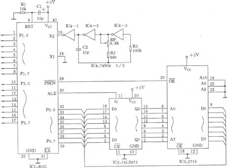
Microcontroller circuit
Published:2011/6/19 1:33:00 Author:John | Keyword: Microcontroller

Microcontroller circuit is as the core control part of the whole system. It notably completies the interface with other circuits, resulting in processing the data. The processing results can be come out in some way, such as being displayed or alarmed. The picture shows the microcontroller circuit.
It can be seen through the figure that microcontroller’s interface circuit is very simple. The general I / 0 interface of microcontroller is respectively connected with interfacs of other circuits. The design of the clock in the microcontroller chip has some other differences with other microcontrollers. MSP430F149 microcontroller has two clock inputs, whose one is a 32kHz clock signal and the other one is an 8MHz clock signal. (View)
View full Circuit Diagram | Comments | Reading(599)
LM139, LM239, LM339 low-power low offset voltage comparator
Published:2011/6/21 5:15:00 Author:Lucas | Keyword: low-power, low offset , voltage comparator
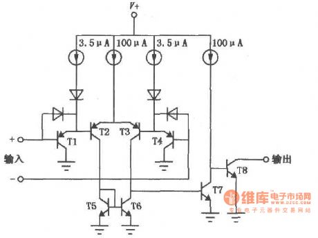
LM139/239/339 is a widely used voltage comparator with excellent performance. It has the features of low power consumption, low offset current, low bias current, and it can supplied by a single power supply, and its output end is compatible with a variety of logic circuits(TTL / DTL / ECL / MOS / CMOS), and each package has four independent comparators. The internal block circuit diagram:
(View)
View full Circuit Diagram | Comments | Reading(1112)
LM119/219/319 double-precision voltage comparator
Published:2011/6/21 6:19:00 Author:Lucas | Keyword: double-precision, voltage comparator
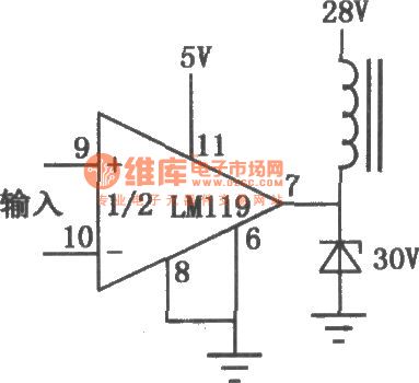
Each package of LM119/219/319 has two separate comparators, which can be supplied by a single 5V power supply. It has high conversion speed, low input bias current, and the output section has a separate ground leading terminal, and the output is compatible to TTL / RTL / DTL capacitors. LM119/219/319 has the high sensitivity, which can be used to compare the the weak signals. It is the precision voltage comparator with higher output power, and it is widely used in control, measurement and other electronic systems. The circuit shown as the chart is the driving relay circuit.
(View)
View full Circuit Diagram | Comments | Reading(546)
Systematic temperature acquisition circuit
Published:2011/6/19 0:54:00 Author:John | Keyword: temperature acquisition

It can be seen through the figure that acquisition circuit is simple and practical.To reduce the effects from the power supply’s input ripple, a 0.1μF capacitor is added on the pin of the power supply so as to achieve filtering function. Thus the disruption for the input end can be reduced.
figure: Systematic temperature acquisition circuit (View)
View full Circuit Diagram | Comments | Reading(389)
AM685 ultra-high-speed voltage comparator
Published:2011/6/21 6:14:00 Author:Lucas | Keyword: ultra-high-speed, voltage comparator
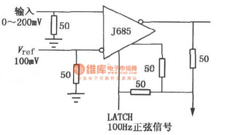
AM685 has a complementary ECL output signal and 5012 linear drive capability; it uses the dual in-line multi-layer metal hermetic package. AM685 is widely used in automatic control, precision instruments and other electronic systems, and high-speed pulse modulator is shown as the chart.
(View)
View full Circuit Diagram | Comments | Reading(808)
system display circuit
Published:2011/6/17 11:28:00 Author:John | Keyword: system display

It can be seen from the figure, the display circuit is directly connected with the MCU data I / O port. As MSP430F149 has a wealth of I / O port resources, such parallel interface mode is very easy. Such reduces complexity of system’s design and also increases the reliability of the system. P4.0 ~ P4.6 is used to display data, P2.1 is used to control the display of the decimal point and P2.2, P2.3 and P2.4 are used to control strobe state of the digital tube. If it is expected to be displayed on DIS0, high electricity level is given on pin of P2.2 and strobe state can be displayed through transistor digital tube.
figure: system display circuit (View)
View full Circuit Diagram | Comments | Reading(493)
LM111, LM211, LM311 single voltage comparator
Published:2011/6/21 6:11:00 Author:Lucas | Keyword: single, voltage comparator
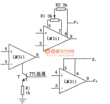
LM111/211/311 supply voltage range (± 5V ~ ± l5V) is high; bias current is low; offset current is low; differential input voltage range (± 30V)is high, and its output is compatible to TTL, DTL and MOS circuit, and it can drive LED and relay. The circuit can use single power supply or dual power supply, and it has two forms of collector output and emitter output. This comparator also has the external balance adjustment and strobe control terminals, which can be used according to choice or adjustment. The basic use of the circuit is shown as the chart.
(View)
View full Circuit Diagram | Comments | Reading(2165)
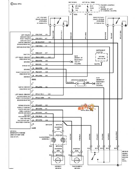
Mazda 94THUNDERBIRD sunroof circuit
Published:2011/6/21 0:21:00 Author:John | Keyword: sunroof

Mazda 94THUNDERBIRD sunroof circuit is shown.
(View)
View full Circuit Diagram | Comments | Reading(1025)
Mazda 94THUNDERBIRD power window circuit
Published:2011/6/21 0:22:00 Author:John | Keyword: power window
Mazda 94THUNDERBIRD power window circuit is shown.
(View)
View full Circuit Diagram | Comments | Reading(578)
Mazda 94THUNDERBIRD (4.6L) starting circuit
Published:2011/6/21 0:22:00 Author:John
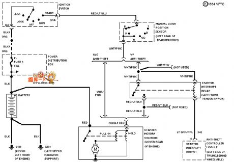
Mazda 94THUNDERBIRD (4.6L) starting circuit is shown.
(View)
View full Circuit Diagram | Comments | Reading(516)
Mazda 94THUNDERBIRD (non-program-controlled suspension) electronic power steering circuit
Published:2011/6/21 0:22:00 Author:John | Keyword: electronic power steering
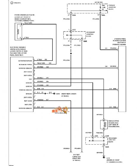
Mazda 94THUNDERBIRD (non-program-controlled suspension) electronic power steering circuit is shown.
(View)
View full Circuit Diagram | Comments | Reading(822)
The application circuit of HA7210 programmable crystal oscillator
Published:2011/6/20 8:27:00 Author:Lucas | Keyword: application circuit , programmable, crystal oscillator
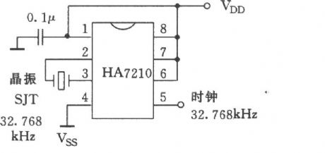
View full Circuit Diagram | Comments | Reading(525)
Multi-road phase shift signal generator
Published:2011/6/20 8:20:00 Author:Lucas | Keyword: Multi-road , phase shift, signal generator
View full Circuit Diagram | Comments | Reading(489)
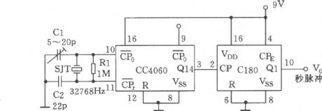
Seconds signal generator composed of CC4060
Published:2011/6/20 8:22:00 Author:Lucas | Keyword: Seconds, signal generator
View full Circuit Diagram | Comments | Reading(454)
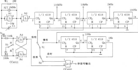
Seconds signal processing circuit(CC4518,CC4001)
Published:2011/6/20 8:25:00 Author:Lucas | Keyword: Seconds , signal processing
View full Circuit Diagram | Comments | Reading(513)
Mazda 95TAURUS (3.2L, SHO) cruise control circuit
Published:2011/6/21 0:36:00 Author:John | Keyword: cruise control
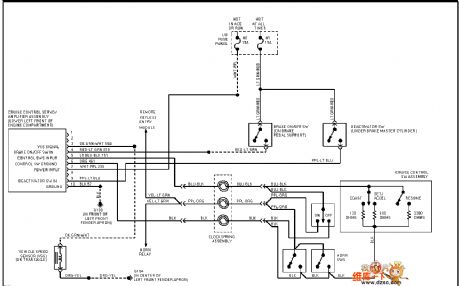
Mazda 95TAURUS (3.2L, SHO) cruise control circuit is shown.
(View)
View full Circuit Diagram | Comments | Reading(579)
Precise second pulse signal generator
Published:2011/6/20 8:30:00 Author:Lucas | Keyword: Precise , second, pulse signal, generator

View full Circuit Diagram | Comments | Reading(616)
Audio preamplifier circuit
Published:2011/6/16 6:25:00 Author:John | Keyword: Audio preamplifier
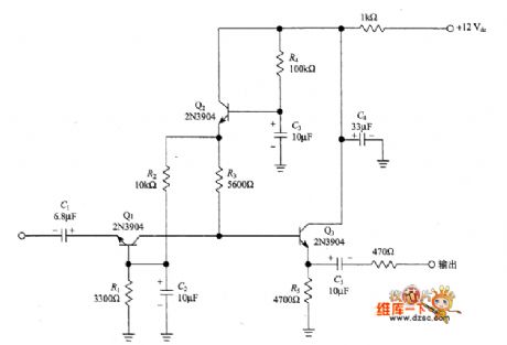
The following figure shows the audio preamplifier matched with 50Ω, which is an improved version of Lawellen circuit. Just as Campbell said, the gain of this circuit is about 40dB and noise value is about 5dB. And the range of input signals has no intention to disturbances (10nV ~ 10mV). These specifications make it available as the amplifier matched with DBM. Just as Lawellen’s circuit, Campbell also uses circuit with the grounded-base input amplifier (Q1) and active isolators (Q2). Beside, an emitter follower / buffer amplifier (Q3) is added.
(View)
View full Circuit Diagram | Comments | Reading(1233)
SBL-1-1 DBM top-level direct conversion receiver audio mixer circuit
Published:2011/6/16 10:28:00 Author:John | Keyword: audio mixer, direct conversion receiver
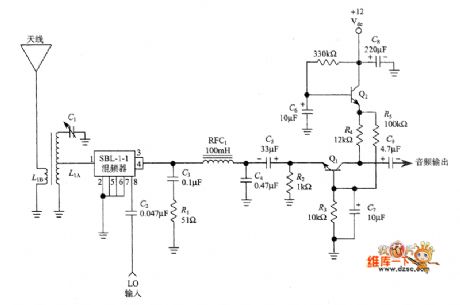
The following figure shows the Lawellen’s another simplified design (original design includes QRP transmitter and DCR). This designed front-end circuit includes an RF and a tuned secondary transformer (L1A). Secondary transformer is raised to resonant state through capacitor C1 and is contacted with 50Ω. Such is to match the input impedance with double-balanced mixer (DBM: Double Balanced Mixer).
DBM used here is Mini-Circuits SBL-1-1. But for the original DBM, Lawllen form it by combining the toroidal transformer and the diode. (View)
View full Circuit Diagram | Comments | Reading(8462)
| Pages:1716/2234 At 2017011702170317041705170617071708170917101711171217131714171517161717171817191720Under 20 |
Circuit Categories
power supply circuit
Amplifier Circuit
Basic Circuit
LED and Light Circuit
Sensor Circuit
Signal Processing
Electrical Equipment Circuit
Control Circuit
Remote Control Circuit
A/D-D/A Converter Circuit
Audio Circuit
Measuring and Test Circuit
Communication Circuit
Computer-Related Circuit
555 Circuit
Automotive Circuit
Repairing Circuit