Signal Processing
The frequency multiplier circuit
Published:2011/6/22 6:27:00 Author:qqtang | Keyword: frequency multiplier | From:SeekIC

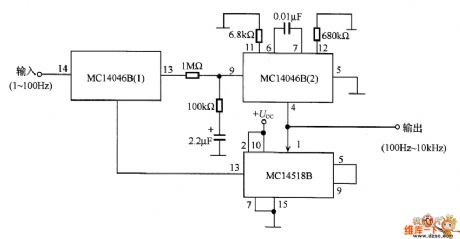
In the figure is the frequency multiplier circuit, the output signal frequency is 100 times of the input one, the frequency range is 1~100Hz. In the circuit, the phaser is MC14046B (1), the voltage control oscillator is MC14046B (2). The voltage control oscillator does the 100 frequency splitting with the 2-bit decimal counter inside it, and the output signal is compared with the input signal which makes the phase synchronize.
This circuit is used to precisely count the low frequency signals which are generated by living organisms in a short time, or used in control pulses of power control acquirement and power supply frequency synchronization.
Reprinted Url Of This Article:
http://www.seekic.com/circuit_diagram/Signal_Processing/The_frequency_multiplier_circuit.html
Print this Page | Comments | Reading(3)

Article Categories
power supply circuit
Amplifier Circuit
Basic Circuit
LED and Light Circuit
Sensor Circuit
Signal Processing
Electrical Equipment Circuit
Control Circuit
Remote Control Circuit
A/D-D/A Converter Circuit
Audio Circuit
Measuring and Test Circuit
Communication Circuit
Computer-Related Circuit
555 Circuit
Automotive Circuit
Repairing Circuit
Code: