Basic Circuit
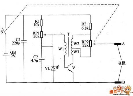
Biological taking poison device circuit diagram 2
Published:2011/6/18 22:45:00 Author:Lucas | Keyword: Biological , taking poison device | From:SeekIC

The biological taking poison device circuit is actually low-frequency oscillator circuit which is composed of the transistor V, pulse transformer T and the realted external components, and the circuit is shown in the chart. Adjusting the resistance of RP1 can change the working frequency of low-frequency oscillator. Regulation the resistance of RP2 can change the output pulse voltage amplitude (ie, the intensity of electrical pulses). R1 and R2 select 1/4W gold film resistors. RPI uses WH-15 series of small synthetic membrane potentiometer without switch; RP2 uses WH-15 series of small synthetic carbon film potentiometer with switch. C1 and C2 select the aluminum electrolytic capacitor with the voltage in 16V. VL chooses Φ3mm red light-emitting diode.
Reprinted Url Of This Article:
http://www.seekic.com/circuit_diagram/Basic_Circuit/Biological_taking_poison_device_circuit_diagram_2.html
Print this Page | Comments | Reading(3)

Article Categories
power supply circuit
Amplifier Circuit
Basic Circuit
LED and Light Circuit
Sensor Circuit
Signal Processing
Electrical Equipment Circuit
Control Circuit
Remote Control Circuit
A/D-D/A Converter Circuit
Audio Circuit
Measuring and Test Circuit
Communication Circuit
Computer-Related Circuit
555 Circuit
Automotive Circuit
Repairing Circuit
Code: