power supply circuit
The typical application circuit of 3-terminal IC
Published:2011/6/19 3:03:00 Author:Seven | Keyword: typical application circuit, 3-terminal IC | From:SeekIC
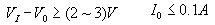
The fixed typical application circuit of 3-terminal IC is shown in the figure. In the figure, C1 and C2 are used for frequency compensation to avoid self-oscillation and high-frequency noise; C3 is a polymer capacitor, and it can weaken the effect, which is from the low-frequency imported by the power supply, on the output voltage; D is a protection diode, when the input terminal is short, it can offer C3 a discharging circuit to stop the voltage on C3 breaking down the emitter of the regulating device.
The requirement of the 3-terminal regulated IC circuit is:
Reprinted Url Of This Article:
http://www.seekic.com/circuit_diagram/Power_Supply_Circuit/The_typical_application_circuit_of_3_terminal_IC.html
Print this Page | Comments | Reading(3)

Article Categories
power supply circuit
Amplifier Circuit
Basic Circuit
LED and Light Circuit
Sensor Circuit
Signal Processing
Electrical Equipment Circuit
Control Circuit
Remote Control Circuit
A/D-D/A Converter Circuit
Audio Circuit
Measuring and Test Circuit
Communication Circuit
Computer-Related Circuit
555 Circuit
Automotive Circuit
Repairing Circuit
Code: