555 Circuit
Cascade amplifier circuit
Published:2011/6/17 9:56:00 Author:John | Keyword: Cascade amplifier | From:SeekIC

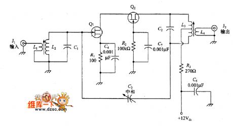
Cascade amplifier is as shown in the figure. The amplifier uses two transistors (both JFET). Q1 is common source configuration and Q2 is a total gate configuration. These two tubes are direct-coupled with each other. The input and output is tuned by a pair of LC filter. (L2C1Ct and L3C2). To avoid the occurrence frequency oscillation in the circuit, a capacitor (C3) 9 is connected to LC filter between the input end of Q1 and the output end of Q2.
figure: Cascade amplifier circuit
Reprinted Url Of This Article:
http://www.seekic.com/circuit_diagram/555_Circuit/Cascade_amplifier_circuit.html
Print this Page | Comments | Reading(3)

Article Categories
power supply circuit
Amplifier Circuit
Basic Circuit
LED and Light Circuit
Sensor Circuit
Signal Processing
Electrical Equipment Circuit
Control Circuit
Remote Control Circuit
A/D-D/A Converter Circuit
Audio Circuit
Measuring and Test Circuit
Communication Circuit
Computer-Related Circuit
555 Circuit
Automotive Circuit
Repairing Circuit
Code: