Signal Processing
Simple doubler generator
Published:2011/6/19 2:59:00 Author:Lucas | Keyword: Simple, doubler, generator | From:SeekIC

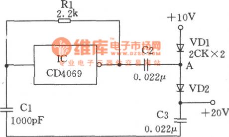
The simple doubler circuit composed of CMOS NOT gate is shown as the chart. The IC in the chart is the inverter and the inverter, Rl, Cl form a square wave oscillator with the frequency about l00kHz, and the oscillator output changes between 0 ~ 10V. When the output is 0V, the capacitor charges to 10V by VD1, when oscillator output changes into +10 V from 0V in a sudden, because the voltage across the capacitor can not change suddenly, the A end of capacitor C2 should be improved accordingly to +20 V, then VDl is reverse-biased, and the current through the VD2 charge to C3, so the output end gets +20 V voltage. But taking into account the diode has voltage drop, so the actual output is slightly lower than +20 V.
Reprinted Url Of This Article:
http://www.seekic.com/circuit_diagram/Signal_Processing/Simple_doubler_generator.html
Print this Page | Comments | Reading(3)

Article Categories
power supply circuit
Amplifier Circuit
Basic Circuit
LED and Light Circuit
Sensor Circuit
Signal Processing
Electrical Equipment Circuit
Control Circuit
Remote Control Circuit
A/D-D/A Converter Circuit
Audio Circuit
Measuring and Test Circuit
Communication Circuit
Computer-Related Circuit
555 Circuit
Automotive Circuit
Repairing Circuit
Code: