
Circuit Diagram
Index 1613
Current / frequency conversion circuit composed of MAX471
Published:2011/7/5 20:12:00 Author:Lucas | Keyword: Current conversion, frequency conversion
The circuit input current range is lO0mA to lA, and the output frequency is proportional to the input current. In the circuit, MAX471 is the high-end current detection integrated circuit, and the ratio between output current and load current is 1:2000. If the load current is lA, the output current is 0.5 mA. When MAX471 output is in high level, it will charge for Cl, and charging voltage rises in slash. MAX952 is a versatile integrated circuit chip, which includes the 1.2 V reference voltage (accuracy is 2%), comparator, operational amplifier and so on.
(View)
View full Circuit Diagram | Comments | Reading(482)
Isolated current / frequency conversion circuit
Published:2011/7/5 20:36:00 Author:Lucas | Keyword: Isolated , current conversion , frequency conversion
The circuit uses the high noise isolation circuit to play a role of isolation, and it will convert current into 0-IOkHz frequency, which is output by the optical coupler TLP521. The circuit iscomposed of the voltage ratio and current / voltage conversion parts. LM331 voltage frequency could convert the voltage into frequency; current / voltage conversion uses the resistor Rl to generate the voltage at both ends (1-5V), and it is converted into 0 -10V voltage by Al (gain is set to 2.5 times). (View)
View full Circuit Diagram | Comments | Reading(489)
555 film showing automatic protection closing down circuit
Published:2011/6/12 22:30:00 Author:TaoXi | Keyword: 555, film showing, automatic protection, closing down
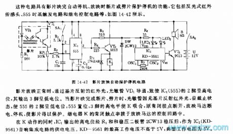
This kind of circuit is composed of the reflective type infrared sensor head, the 555 time-base trigger circuit and the relay control circuit.etc, as the figure 14-42 shows.
When the film is projecting, the infrared light which is reflected by the substrate conducts the photosensitive tube VD1 to make the pin-2 of IC1(555) to have the high electric potential, the output port pin-3 has the low electric potential. Then the film is over or interrupt, the photosensitive tube is in the cut-off state because of there is no reflection infrared ray, the 555's pin-2 has the low electric potential, the 555 sets, pin-3's high electrical level makes the K to close, the normally closed contact point cuts off, the screening motor has no power to work.
The normally closed contact point of relay K connects with the screening motor's control circuit.
(View)
View full Circuit Diagram | Comments | Reading(474)
Current/frequency conversion circuit
Published:2011/7/5 8:28:00 Author:Lucas | Keyword: Current/frequency conversion
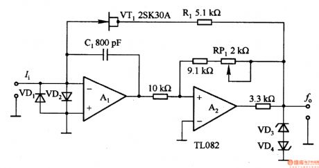
In the circuit, Al is integral circuit. When it has the current input, the integrator capacitor integrates to a negative direction. A2 output voltage is clamped by regulator diodes VD3 and VD4, so Al is inverted when the output is about -5 · 6V, after VTl is turned on, the integral voltage outputs rapidly until being inverted at +5 · 6V. Al output rising time depends on the clamping voltage, resistor Rl and the integrating capacitor Cl, and reducing the input current Ii and Cl time constant can decrease the rising time. Oscillation frequency is mainly decided by the input current and C1.
(View)
View full Circuit Diagram | Comments | Reading(1146)
Resistance/voltage transform circuit
Published:2011/7/5 8:21:00 Author:Lucas | Keyword: Resistance/voltage transform
This circuit is actually a resistance meter, which can directly indicate resistance. A2 is an inverting amplifier, and Rx is connected in the feedback loop. If the offset voltage and input bias current source can be ignored, the A2 output voltage U. =- UR (Rx / Rs), and it can find Rx = Rs /-URo to select the reference resistor Rs to get a fixed reference voltage, then the output voltage U. is the measured resistance, which can be directly read out. Rs is divided in the range of 2OOΩ -2MΩ with the unit in 10 times, and converted into 0-2V voltage output.
(View)
View full Circuit Diagram | Comments | Reading(550)
High output voltage/current conversion circuit
Published:2011/7/5 20:30:00 Author:Lucas | Keyword: High output , voltage conversion, current conversion

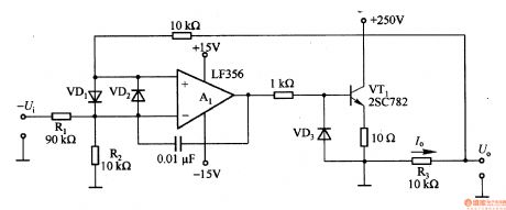
The circuit uses the floating ±15V +250 V power supply to get load voltage which is greater than 2OOV. Input voltage U is 0 -lOV, which could be 0-1V divided by R1 and R2. It is assumed that Al inverting input voltage is -lV, the ground potential is a benchmark, the Al output is placed forward and VTl has base current flowing, so the output end voltage increases, then current f. = LV/R3 through the load. When I. R3 =- lV, the loop is stable, if R3 changes in the range of 0.1 - lOkΩ, it can be converted into the current with the range of lOmA to l0OμA .
(View)
View full Circuit Diagram | Comments | Reading(602)
Temperature/frequency conversion circuit
Published:2011/7/5 20:22:00 Author:Lucas | Keyword: Temperature conversion, frequency conversion
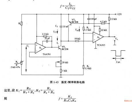
In the circuit, the temperature sensor uses thermistor RT, and RT and resistor R2 form the voltage divider circuit to make resistance / temperature characteristic in linear relationship. The voltage Ui is proportional to the temperature, and it is changed into charging current IL for capacitor CT by Al and VT1. A2 could compare the voltage of URl and UCT, when UCT <URl, A2 outputs low level, VT1 is deadline, CT is charged in the current IL; when UCT ≥ UR1, A2 output is high, so that VT2 is saturated conduction, CT is discharged by VT2.
(View)
View full Circuit Diagram | Comments | Reading(533)
555 TV programs monitoring and timing conversion circuit
Published:2011/6/16 1:11:00 Author:TaoXi | Keyword: 555, TV programs, monitoring, timing, conversion circuit

When the switch K2 of the additional circuit is in the position 1 , the astable multivibrator is composed of the 555 and R1, R2, C1, because the charging time of the circuit tcharging=0.693(R1+R2)C1, it is larger than the discharging time td=0.693R2C1, so the duty ratio of the output pulse is small, this circuit can realize the main channel long-time display (about 10 minutes) and the vice channel short display (about 5 seconds). When the K2 is in the position 2 , the monostable timing circuit is composed of the 555 and R3, VT, RP, C2. The constant current source is composed of the MOSFET 3DJ6, this constant current source charges the C2 to improve the timing accuracy. By adjusting RP, you can pre-set the timing time (5 to 90 minutes). When this circuit is used as the timing circuit, you need to press AN to set the 555 circuit, so the timing starts.
(View)
View full Circuit Diagram | Comments | Reading(674)
Numerical control triangle wave-square wave generator circuit
Published:2011/6/27 2:51:00 Author:TaoXi | Keyword: Numerical control, triangle wave, square wave, generator circuit
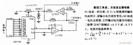
Numerical control triangle wave-square wave generator circuit: the integrator is composed of the N1, it integrates the output current of the D/A converter to change the output voltage linearly; the voltage comparator is composed of the N2, its output voltage is limited by the two-way voltage diode 2DW7from +6.5Vto -6.5V.
(View)
View full Circuit Diagram | Comments | Reading(783)
Voltage / current and current / voltage conversion circuit composed of NJM4558
Published:2011/7/5 20:06:00 Author:Lucas | Keyword: Voltage / current, current / voltage , conversion
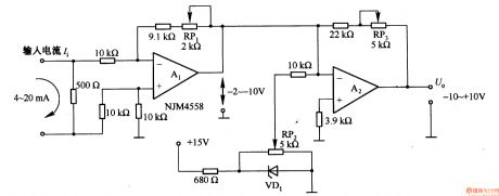
Figure 1-42 (a) is a voltage / current conversion circuit, and it can convert 0-lOV input voltage into 4-2OmA output current. Adjusting RP2 could make Ui = 0, I. = 2OmA; adjusting RP2 could make Ui = lOV, I. = 4mA. Figure 1-42 (b) is the current / voltage conversion circuit, which will convert the 4-2OmA current into -10 to + lOV output voltage. Adjusting RP1 could make the A1 output -2 to -lOV; adjusting RP3 could make the A2 output -10 to +10 V; adjusting RP1 could make the bias voltage of A2 in +6 V.
(View)
View full Circuit Diagram | Comments | Reading(5264)
Midea household automatic dishwasher circuit
Published:2011/6/23 20:49:00 Author:TaoXi | Keyword: Midea, household, automatic dishwasher

The working principle of the dishwasher: the dishwasher uses the electrical motor to drive the wash pump to form the water with 3m injection pressure, the water is pressured by the wash pump and is heated by the heating tube, then it is jetted by the blowhole of the sprinkler. Because the reaction force of the water spray adds to the sprinkler to make it to turn constantly, this makes the water column which is sprayed on the top of the dishwasher to have the large recoil force, the spray arm constantly sprays the hot-water which has the detergent or bleaching lotion on the tableware surface from the three-dimensional direction densely.
(View)
View full Circuit Diagram | Comments | Reading(1612)
Resistance/voltage transform circuit composed of TL082
Published:2011/7/5 8:33:00 Author:Lucas | Keyword: Resistance/voltage transform
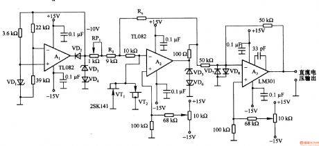
Al and VD1 constitute constant current source circuit, and Al outputs a constant output voltage, which is the key of resistance/voltage transform circuit, and it can transform -lOV reference voltage into current by reference resistance (R (RP1)+ R1). Since (R (RP1) + R1) resistance is lOkΩ, -lOV reference voltage can get lmA reference current. lmA base current flowing through resistor RX is converted into a corresponding voltage, which is output by buffer amplifier A3, then it will convert resistor RX to the corresponding voltage. In the circuit, the VD3-VD8 and VTl, VT2 constitute a protection circuit.
(View)
View full Circuit Diagram | Comments | Reading(3605)
Quartz crystal rectangular wave oscillator circuit
Published:2011/6/27 2:51:00 Author:TaoXi | Keyword: Quartz crystal, rectangular wave, oscillator circuit

The quartz crystal rectangular wave oscillator circuit is mainly used in the new digital system clock-pulse generator. When the quartz crystal of this circuit is in the resonant state, the transmission amount is the largest, now the harmonic oscillation rate of the quartz crystal is the crystal's harmonic oscillation rate. Because ofthe high output impedance of LM111 and the isolation effect of C2, so the load of the quartz crystal is very small. The stability of the oscillation frequency is high. The circuit has the 100KHz rectangle wave output.
(View)
View full Circuit Diagram | Comments | Reading(2102)
Agricultural automatic water valve circuit diagram 1
Published:2011/6/18 21:56:00 Author:Lucas | Keyword: Agricultural, automatic , water valve
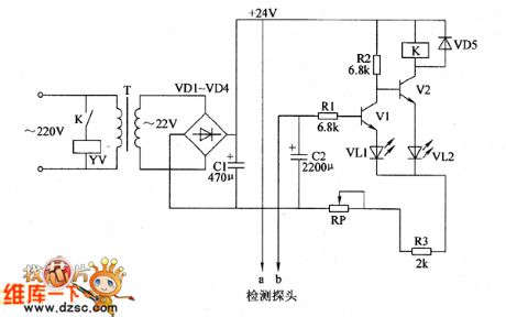
Agricultural automatic water valve circuit is composed of the power supply circuit, detection circuit and control circuit, and the circuit is shown as the Figure 1. Power supply circuit is composed of the power transformer T, rectifier diodes VD1 ~ VD4 and filter capacitor C1. The detection circuit is composed of the water level probe and resistor R3 and so on. Control circuit consists of transistors V1, V2 and the relay K and other components. AC 220V voltage is bucked by T, rectified by VD1 ~ VD4 and filtered by C1 to produce DC voltage with about 24V for the control circuit. R1 ~ R3 select 1/4W carbon film resistors. VD1 ~ VD5 select 1 N4007 silicon rectifier diodes.
(View)
View full Circuit Diagram | Comments | Reading(712)
The drainage and irrigation station remote controller circuit diagram
Published:2011/6/18 21:55:00 Author:Lucas | Keyword: drainage , irrigation , station , remote controller

The drainage and irrigation station remote controller circuit consists of water pump motor M, knife switch Q, fuses FU1, FU2, AC contactor KM, thermal relay KR, control buttons S1 ~ S4, incandescent bulb HL and signal lines, and the circuit is shown as the Figure. Start button S3 and stop button S4 are installed in the control room to connect to the water pump motor circuit in drainage and irrigation station by the signal lines. It the farmland needs to stop the irrigation, people should press S4 to make the KM release because of two ends of coil being connected to L2-phase power, then the pump motor M stops.
(View)
View full Circuit Diagram | Comments | Reading(1863)
Electronic pests repeller circuit diagram 1
Published:2011/6/12 22:54:00 Author:Lucas | Keyword: Electronic, pests repeller
The electronic pests repeller circuit is composed of the clock oscillator, counter, multivibrator and the audio output circuit, and the circuit is shown as the chart. Power supply circuit is composed of the power transformer T, rectifier diodes VD1 ~ VD4 and filter capacitor C1. Multivibrator is composed of the time-base IC IC1 and resistors R1, R2, capacitors C2, C3. C4 is the coupling capacitor; BL is the speaker. The AC 220V voltage bucked by T, rectified by VD1 ~ VD4 and filtered by C1 to produce 12V (Vcc) DC voltage for IC. When the multivibrator gets power and does oscillation work, the pin 3 will output 48KHz square wave, which is changed into the ultrasonic by BL radiated outward, then it can drive away near the pests.
(View)
View full Circuit Diagram | Comments | Reading(498)
Agricultural submersible pump burglar alarm circuit diagram
Published:2011/6/12 22:55:00 Author:Lucas | Keyword: agricultural , submersible pump, burglar alarm

The agricultural submersible pump burglar alarm circuit is composed of the relay K, diodes VD1, VD2, power transformer T and bell HA, and the circuit is shown as the chart. When the submersible pump is stolen or disconnected because of other reasons, the power supply loop of relay K is cut off, and the normally closed contact is connected, then HA produces alarm sound. VD1 and VD2 use 1N5402 silicon rectifier diode or 2CP35B ordinary silicon diodes. HA chooses the alarm bell with working voltage being 380V. K selects JQX-4 24V DC relay. KM uses CDC10 380V AC contactor. T uses the power transformer with 3 ~ 5W, 25 ~ 30V secondary voltage(380V/25 ~ 30V). S1 selects moving off button; S2 selects portfolio button (each grous of moving on, moving off contacts). Fuse FU1, knife switch Q and the thermal relay KR should be selected according to the rated power of M; FU2 uses 2A fuse.
(View)
View full Circuit Diagram | Comments | Reading(2631)
Electronic pests killing lamp circuit diagram 3
Published:2011/6/12 22:56:00 Author:Lucas | Keyword: Electronic, pests killing lamp

The electronic pests killing lamp circuit consists of the power switch S, trap lamp HL, high-voltage electrode, capacitors C1 ~ C5 and diodes VD1 ~ VD5, and the circuit is shown as the chart. In the circuit, C1 ~ C5 and VDI ~ VD5 form the 5 times voltage doubling rectifying circuit. Turning on the power switch s will make HL get power and light, and the AC 220V voltage which is 5 times doubled rectified by the voltage rectifier circuit can generate the DC pulse voltage with about 1400V, which is added to the high-voltage electrode. When the insects fly to trap lamp, touch or near high-voltage electrodes, they will be killed by high voltage electrodes. C1 ~ C5 select polyester or CBB capacitors with the voltage being 630Y. VD1 ~ VD5 use 1N4007 silicon rectifier diodes. S uses 3 ~ 5A, 220V AC power switch. HL uses black light or special anti-mosquito lamp.
(View)
View full Circuit Diagram | Comments | Reading(4832)
Telephone line burglar alarm circuit diagram
Published:2011/6/30 5:36:00 Author:Lucas | Keyword: Telephone line, burglar alarm

The breakover of T2 makes T3 breakover, and then the rear audio oscillation circuit, and LED, DY will emit aural and visual alarm, and it can add the interfere signal on out wire by LED, DY , while the voltage of out wire decreases, so those theft callers are forced to hang up as they can not dial. This alarm can monitor and prevent others from unauthorized using of your telephone line. When someone outside connects to your phone line and makes a free call, the alarm will issue the interference signals to forbid thieves from dialing, then it uses sound and light to inform of the owner somone having used the call.
(View)
View full Circuit Diagram | Comments | Reading(1239)
The electronic rodent repeller circuit diagram 3
Published:2011/6/30 5:35:00 Author:Lucas | Keyword: Electronic rodent repeller

The electronic rodent repeller circuit is composed of the power transformer T, diodes VD1 ~ VD6, transistors V1 and V2, thyristor VT, relay K, alarm HA and electrode and so on, and the circuit is shown as the chart. R1 ~ R3 use of 1 / 417 carbon film resistors. C1 and C2 select aluminum electrolytic capacitors with the voltage in 16V. VD1 and VD3 ~ VD5 use 1N4007 silicon rectifier diodes; VD2 uses 1N5408 silicon rectifier diode; VD6 uses 1N4148 silicon switching diode. V1 selects 59012 silicon PNP transistor; V2 selects 59013 silicon NPN transistor. VT selects MCR100-6 thyristor. K selects 6V DC relay. HA selects the speakers or alarm bell with higher loudness . Adjusting the R1 can alter the conduction sensitivity of VT.
(View)
View full Circuit Diagram | Comments | Reading(889)
| Pages:1613/2234 At 2016011602160316041605160616071608160916101611161216131614161516161617161816191620Under 20 |
Circuit Categories
power supply circuit
Amplifier Circuit
Basic Circuit
LED and Light Circuit
Sensor Circuit
Signal Processing
Electrical Equipment Circuit
Control Circuit
Remote Control Circuit
A/D-D/A Converter Circuit
Audio Circuit
Measuring and Test Circuit
Communication Circuit
Computer-Related Circuit
555 Circuit
Automotive Circuit
Repairing Circuit