
Circuit Diagram
Index 1605
Touching delay lamp switch circuit(9)
Published:2011/7/1 2:37:00 Author:Ecco | Keyword: Touching , delay lamp , switch

The chart shows the touching delay lamp for night, if you wake up at night and want to know the time, as long as to touch the small box beside the pillow, small light in box E will be lit and turned off after delaying more than ten seconds.
(View)
View full Circuit Diagram | Comments | Reading(543)
Battery-powered fluorescent lamp circuit (1)
Published:2011/6/30 3:21:00 Author:Ecco | Keyword: Battery-powered, fluorescent lamp

View full Circuit Diagram | Comments | Reading(1480)
Two-dimensional lantern controller circuit analysis and manufacture
Published:2011/6/30 2:59:00 Author:Ecco | Keyword: Two-dimensional , lantern controller , analysis , manufacture


Two-dimensional lantern controller circuit shown in Figure 1 is mainly composed of the NOT gate lCl (CD4069), counting, timing distribution circuit IC2 (CD4017), analog electronic switch IC3 (CD4066) and D trigger IC4 (CD40174). CD4069 logic function and pin is shown in Figure 2a, of which NOT gates F1, F2 and external resistors R2, R3, capacitor C4 form multivibrator to produce a square wave pulse in about 3Hz. R3, C4 are the oscillator timing components. Regulation the two components can change the oscillation frequency.
(View)
View full Circuit Diagram | Comments | Reading(992)
Electronic energy saving lamp (4)
Published:2011/6/30 2:01:00 Author:Ecco | Keyword: Electronic , energy saving, lamp

View full Circuit Diagram | Comments | Reading(700)
DC / DC converter 250W switching power supply circuit diagram composed of TOP249Y
Published:2011/6/30 3:05:00 Author:Ecco | Keyword: DC / DC , converter, 250W , switching power supply

The DC / DC converter switching power supply uses a TOP249Y with input 250V ~ 380V DC, and the output is 48V, 5.2A (250W), then the power efficiency is up to 84%. The circuit is shown in Figure 2. High-frequency filter capacitor C1 is specifically inhibit the input from the electromagnetic interference. As the TOP249 works in its power limit, which need short connect X-side and the source S, within the limit is set the maximum current, that is ILIMIT = ILIMIT (max) = 5.7A.
(View)
View full Circuit Diagram | Comments | Reading(6538)
Classic 0-300MHz no Bote Wan band amplifier circuit diagram
Published:2011/7/1 2:19:00 Author:Ecco | Keyword: Classic , 0-300MHz , no Bote Wan band , amplifier

View full Circuit Diagram | Comments | Reading(650)
Cell phone lithium-ion battery charger circuit diagram
Published:2011/6/30 3:12:00 Author:Ecco | Keyword: Cell phone , lithium-ion, battery charger

View full Circuit Diagram | Comments | Reading(2331)
Nickel cadmium battery charger circuit diagram with timing function
Published:2011/7/1 2:17:00 Author:Ecco | Keyword: Nickel cadmium battery , charger , timing function

View full Circuit Diagram | Comments | Reading(783)
5 v turning to 3.3 v level conversion circuit diagram
Published:2011/6/30 3:11:00 Author:Ecco | Keyword: 5 v , turning , 3.3 v , level conversion

The picture shows the MP2104 circuit produced by the MPSwhich can used inPIN-PIN and RT8008 chip, etc.
(View)
View full Circuit Diagram | Comments | Reading(471)
Discrete sound and light control stairs delay switch circuit(9)
Published:2011/6/30 1:09:00 Author:Ecco | Keyword: Discrete , sound , light , control, stairs delay switch

The unique sound and light control stairs delay switch circuit shown in the Figure has higher sound control sensitivity. at night, when someone walking on the stairs, the footsteps will make electronic switch, lamp light, and after people left, the lights will go off after 30s.
(View)
View full Circuit Diagram | Comments | Reading(954)
Discrete sound and light control stairs delay switch circuit(6)
Published:2011/6/30 1:47:00 Author:Ecco | Keyword: Discrete, sound , light , control , stairs delay switch

The sound and light control stairs delay switch circuit shown as the chart uses an improved piezoelectric ceramics for the sound -power transducer, due to the sensitivity to sound signal of piezoelectric ceramics is lower than electret condenser microphone, the audio amplifier uses VT4 ~ VT6 three voltage amplification to enhance the switch's responsiveness to sound. Circuit delay time is mainly decided by R3, C2, and the icon data is about 1min.
(View)
View full Circuit Diagram | Comments | Reading(789)
High gear stepping dimmer controller circuit (2)
Published:2011/6/28 1:51:00 Author:Ecco | Keyword: High gear, stepping , dimmer , controller

The chart shows the high gear stepping dimmer controller circuit, which has the following functions: It has four gears of stong, medium, weak, extinguish to control the timing of light E1 in 1h, 2h , 4h and 8h; On the other hand, it can control a way of wall lights being in on and off state and another way of fluorescent lights in working state. The device in the core of the circuit is a BA3102 fan control ASIC, and it has three wind-speed control of strong, medium and weak; it has 8h four-stage non-progressive electronic timing(1,2,4,8 h); it has two non-independent control outputs.
(View)
View full Circuit Diagram | Comments | Reading(502)
Simple mixing dimmer circuit
Published:2011/6/28 2:12:00 Author:Ecco | Keyword: Simple, mixing dimmer
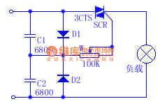
When the capacitor is connected in the sinusoidal AC circuit, the maximum voltage and current will have 90 ° phase difference. According to this theory, the C1 and C2 are connected in series to form the difference, and it is more stable than the connection of resistors and capacitors in series. In the circuit, D1 and D2 rectify respectively positive half-wave and negative half-wave of power, and then it is added to the A trigger and C1 or C2 begins charging. Further using W can change the trigger time for shift-phase, as long as the adjustment of W resistance, you can achieve the purpose of changing the output voltage.
(View)
View full Circuit Diagram | Comments | Reading(504)
The IR2159 integrated electric ballast circuit of adjustable light
Published:2011/7/6 1:16:00 Author:qqtang | Keyword: electric ballast, adjustable light

figure: The IR2159 integrated electric ballast circuit of adjustable light (View)
View full Circuit Diagram | Comments | Reading(626)
The barton automatic fill light circuit
Published:2011/6/27 22:30:00 Author:Ecco | Keyword: barton , automatic, fill light

Providing enough light for hens can increase egg production rate. Due to the short sunshine time in winter, the chicken specialized households generally use the artificial method to fill light. Using the circuit shown as the chart is able to automatically fill light, when night comes, the light will automatically turn on about 2h, then turn off, that is , sunshine time extends about 2h. T uses 220V/15V, 8VA small, high quality power transformer; K uses JZC-22F, DC12V small medium power electromagnetic relay.
(View)
View full Circuit Diagram | Comments | Reading(565)
The temperature control circuit composed of the temperature sensor
Published:2011/7/6 1:21:00 Author:qqtang | Keyword: temperature control, temperature sensor
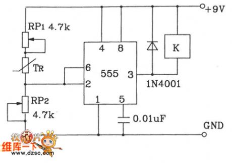
By adjusting RP1 and RP2, the temperature point can be preset, the 555 time-based circuit composes the Schmidt reversal phase circuit, the auto control is fulfilled by using the relay.
(View)
View full Circuit Diagram | Comments | Reading(1103)
The Suzuki Antelope-Century Star sensor parameter and engine ABS/SRS system circuit
Published:2011/7/6 1:40:00 Author:qqtang | Keyword: Suzuki, Antelope-Century Star, sensor parameter

The Suzuki Antelope-Century Star sensor parameter and engine ABS/SRS system circuit is shown as above.
(View)
View full Circuit Diagram | Comments | Reading(1060)
Electronic energy saving lamp (2)
Published:2011/6/30 2:10:00 Author:Ecco | Keyword: Electronic , energy saving, lamp

In the circuit shown as the chart, VT1, VT2 use MTE13005 high-power tube with the same properties. T uses high-frequency magnetic ring with the internal diameter in Φ6mmw and Φ 0.5mm high strength polyester enameled wire around, and L1, L2 have 2 turns, and L3 has 8 turns.
(View)
View full Circuit Diagram | Comments | Reading(1337)
The temperature sensor auto control music play circuit
Published:2011/7/6 1:49:00 Author:qqtang | Keyword: temperature sensor, auto control
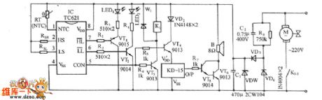
See as the figure, the circuit consists of the temperature sensor and the relay controlled fan motor circuit, temperature limit indicating circuit, music generating circuit and AC step-down circuit, etc. The core part is the TC621 temperature control integrated circuit.
(View)
View full Circuit Diagram | Comments | Reading(571)
Efficient white LED driver circuit
Published:2011/6/28 2:18:00 Author:Ecco | Keyword: Efficient, white LED , driver circuit


1. The white LED can be used in seies, regardless of the number of connection of the LED, a resistor can provide them with a constant current; 2. A LED resistor can adjust the operating current of white LED; 3. Ceramic capacitors can be used to obtain low ripple noise, and extend the life of the circuit; 4.It can greatly reduce circuit space: XC9105 and FET + SD are available in SOT23 packages, nad the maximum coil thickness is only 1.2 mm, the input and output capacitors are ceramic capacitors.
(View)
View full Circuit Diagram | Comments | Reading(909)
| Pages:1605/2234 At 2016011602160316041605160616071608160916101611161216131614161516161617161816191620Under 20 |
Circuit Categories
power supply circuit
Amplifier Circuit
Basic Circuit
LED and Light Circuit
Sensor Circuit
Signal Processing
Electrical Equipment Circuit
Control Circuit
Remote Control Circuit
A/D-D/A Converter Circuit
Audio Circuit
Measuring and Test Circuit
Communication Circuit
Computer-Related Circuit
555 Circuit
Automotive Circuit
Repairing Circuit