
Circuit Diagram
Index 1614
Electric sewing machine no-load economizer circuit diagram 2
Published:2011/6/30 5:27:00 Author:Lucas | Keyword: Electric , sewing machine , no-load , economizer

The electric sewing machine no-load economizer circuit is composed of low-voltage circuit breaker QF, control switch S1, light switches S2 and S4, foot switch S3, AC contactor relay KM and time relay KT, and the circuit is shown as the chart. When the sewing workers continue to work, then move the clutch pedal to turn off S3, KT gets power and resets, KM gets power and pulls in, then M starts running, and they begin sewing work. If it needs lighting during the M stopped time, you can manually turn on light switch S2, the EL light will be lit. S1, S2 use the self-locking power switches with the contact current being more than 5A; S3 uses the protected move off button. KM selects the AC contactor with the coil voltage in 220V, contact current in 10A.
(View)
View full Circuit Diagram | Comments | Reading(2503)
Static Elimination (the 2nd)
Published:2011/7/5 8:38:00 Author:Felicity | Keyword: Static Elimination (the 2nd)

Work of the circuit
The circuit consists of power supply circuit and boost oscillation circuit. (It is showed in the picture 8-118.)
Power supply circuit consists of power switch S1, fuse FU, power transformer Tl, bridge rectifier, UR, filter capacitors Cl and voltage selector switch S2.
Boost oscillation circuit consists of resistors R1-R4, capacitors C2 and C3, diodes VDl-VD6, step-up transformer T2 and transistor Vl, V2. (View)
View full Circuit Diagram | Comments | Reading(522)
The loom electricity saving controller circuit diagarm 6
Published:2011/6/12 22:58:00 Author:Lucas | Keyword: loom , electricity saving controller
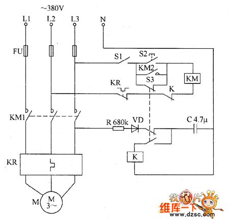
The loom electricity saving controller circuit is composed of the control switch S1, start button S2, AC contactor KM, thermal relay KR, relay K, resistor R, capacitor C, and the micro switch S3, and the circuit is shown as the chart. R uses 1W metal film resistor. C uses the oil condenser or CBB capacitor with the withstang voltage being 250V. VD uses 1N5406 silicon rectifier diode. S1 selects the 380V power switch with contact current being greater than 5A; S2 uses compression press making button; S3 selects limit switch. K selects JQX-10F 24V DC relay. KM selects the AC contact with the coil voltagein 380V, contact current capacityin 15A.
(View)
View full Circuit Diagram | Comments | Reading(625)
The gas limiting alarm miner lamp circuit diagram 4
Published:2011/7/4 22:05:00 Author:Lucas | Keyword: Gas limiting , alarm , miners lamp

The gas limiting alarm miner lamp circuit is composed of the gas detection circuit, multivibrator, audio output circuit and the lighting circuit, and the circuit is shown as the chart. Gas detection circuit is composed of the gas sensor and resistors R2, R3. Multivibrator is composed of the two NAND gates D1, D2 which are inside of the NOT gate IC and resistors R4 and R5, capacitor C2. Audio output circuit consists of resistor R6, audio amplification tube V and speaker BL. Lighting circuit is composed of the battery GB, illuminating lamp EL and light switch S. R1 uses 1/2W carbon film resistor; R2 uses small sealed variable resistor; R3 ~ R6 select 1/4W carbon film resistors.
(View)
View full Circuit Diagram | Comments | Reading(810)
MAX866 converter, main features and pin of power supply monitor
Published:2011/7/4 22:33:00 Author:Lucas | Keyword: converter, main features , pin , power supply monitor
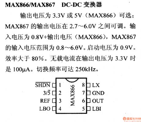
MAX866/MAX877DC-DCconverter
Output voltage is 3.3V or 5V (MAX866) ; MAX867's output voltage is adjustable between 2.7 ~ 6.0V. Output voltage is 0.8V, MAX866's output voltage range is 0.8 ~ 6.0V. Starting voltage is 0.9V. Efficiency is greater than 80%. No-load current is 100μA when the output voltage is 3.3V. Switching frequency is up to 250KHZ.
(View)
View full Circuit Diagram | Comments | Reading(536)
MC3423 overvoltage protection circuit, main features and pin of power monitor
Published:2011/7/4 22:34:00 Author:Lucas | Keyword: overvoltage , protection circuit, main features , pin , power monitor


MC3423/3523 over-voltage protection circuitIt is a controllable circuit which is used for external arc extinction to detect over-voltage of main power supply voltage; it can change the detection voltage; output current is 300mA; control terminal is TTL level; it is embedded 2.6V voltage reference circuit; the maximum voltage difference between VCC and VEE ends is 40V; the maximum input voltage of detection end is 6.5V and the maximum input voltage of remote activation terminal is 7V; MC3423 operating temperature is 0 ~ 70 ℃, MC3523 is -55 ~ +125 ℃; MC3423 has the ceramic sealing, plastic and micro-encapsulation packages, MC3423 has the ceramic sealing and micro-encapsulation package.
(View)
View full Circuit Diagram | Comments | Reading(1009)
Temperature Controller (the 1st)
Published:2011/7/5 10:18:00 Author:Felicity | Keyword: Temperature Controller (the 1st)

Work of the circuit
The circuit consists of power circuit and temperature detection control circuit. (It is showed in picture 8-105.)
Power circuit consists of power switch S, fuse FU, power transformer T, bridge rectifier, UR, filter capacitors Cl and C2, three-terminal voltage regulator integrated circuit IC, current-limiting resistor R and the power indicator LED VL.
Temperature detection control circuit consists of electric contact thermometers Q, relay Kl, K2, KM and AC contactor heater EH. (View)
View full Circuit Diagram | Comments | Reading(853)
Automatic switching circuit of voltage and current control mode
Published:2011/7/4 22:12:00 Author:Lucas | Keyword: Automatic , switching , control mode
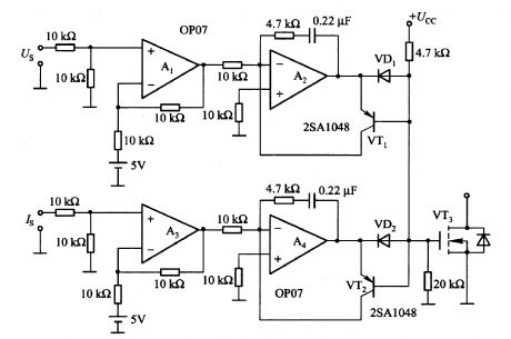
Al and A2 form the voltage control mode, and Us is the load output voltage detection signal, A3 and A4 constitute the current control mode, and IS is the load current detection signal. The circuit can switch automatically according to the voltage and current detection signals. For example, in the voltage control range, the VD1 conduction, VT1 does not work. Then the output of A4 increases, if it reaches the base current level of VT2, the VT2 conduction, then the A4 is added negative feedback by VT2.
(View)
View full Circuit Diagram | Comments | Reading(3139)
The power MOSFET isolated gate drive circuit
Published:2011/7/4 22:10:00 Author:Lucas | Keyword: MOSFET , isolated gate , drive circuit

In the circuit, the pulse signal of input A and input B is from the TL494 or UC3852 switching power supply integrated controller. T1 and T2 are the pulse transformers, which aim for high-voltage isolation and to enhance the noise immunity to make high power switching circuit work reliably. The duty cycle range of the circuit is 0% to 45%. Power MOSFET switching characteristics are related to gate driving capacity, here VT3 and VT4 use PNP transistors.
(View)
View full Circuit Diagram | Comments | Reading(6184)
DC power on / off switch circuit
Published:2011/7/4 22:09:00 Author:Lucas | Keyword: DC power , on-off switch

It is the switch circuit with the input voltage in +6 to +14 V, load current I in lOA. Minimum input voltag is decided by the used MOSFET (VTl) gate threshold voltage. VT2 collector current is decided by the required switching speed. If it uses P-channel power MOSFET, the gate resistance can be high because of IC being small, so the current consumption can be low. If the open speed is faster, the drain current is large. When conditions are bad, it can be connected capacitor between gate - source pole of VTl.
(View)
View full Circuit Diagram | Comments | Reading(8534)
Power MOSFET gate drive circuit composed of transistor
Published:2011/7/4 22:08:00 Author:Lucas | Keyword: Power MOSFET gate , drive circuit , transistor

The circuit consists of two forward converters: one is the charging converter for power MOSFET gate capacitor; the other is discharging converter gate for the gate capacitor. Recommended power supply voltage is 12 to 15V. On the rising edge of the drive pulse, VT5 receives pulse, for the figure given the values of Cl and Rl, the typical duration time is 2OOns, and the pulse is transmitted to the secondary stage of transformer Tl. When VT6 and VD3 are in the appropriate offset, the secondary pulse will charge for the gate - source capacitor of driven power MOSFET, then shut down the current path.
(View)
View full Circuit Diagram | Comments | Reading(8179)
Static Elimination (the 1st)
Published:2011/7/5 8:37:00 Author:Felicity | Keyword: Static Elimination (the 1st)

Work of the circuit
The circuit consists of l2V power supply circuit, the output pulse voltage step-up circuit and LED indicator circuit. (It is showed in the picture 8-117.)
l2V power supply circuit consists of power transformer Tl, bridge rectifier, UR, filter capacitors Cl and three-terminal voltage regulator integrated circuit ICl.
The output pulse voltage step-up circuit consists of resistors Rl-R5, capacitors C2-C5, thyristor VT, potentiometer RP, diode VDl-VD3 and step-up transformer.
LED indicator circuit consists of resistors R6-R13, light emitting diodes VLl-VL4 and operational amplifier integrated circuit IC2 (Nl-N3). (View)
View full Circuit Diagram | Comments | Reading(525)
Temperature Controller (the 6th)
Published:2011/7/5 10:24:00 Author:Felicity | Keyword: Temperature Controller (the 6th)

Work of the circuit
The circuit consists of power supply circuit, temperature measurement and control circuit, LED temperature indicator circuit and heater control circuit. (It is showed in picture 8-110.)
Power supply circuit consists of power transformer T, rectifier diode VDl-VD4, three-terminal voltage regulator integrated circuit IC5 and filtering capacitors Cl.
Temperature measurement and control circuit consists of temperature sensor IC lCl, temperature control selector switch S, three-terminal regulator IC lC2 and resistors Rl-R6.
LED temperature indicator circuit consists of voltage reference integrated circuit IC3, LED display driver IC lC4, resistors R8-Rl3 and light-emitting diode VLl-VLlO.
Heater control circuits consists of resistor Rl4, R15, capacitor C2, non-gate integrated circuit IC6 (D1-D4), solid state relays KN, KM and AC contactor heater EH.
(View)
View full Circuit Diagram | Comments | Reading(1169)
Temperature Controller (the 5th)
Published:2011/7/5 10:23:00 Author:Felicity | Keyword: Temperature Controller (the 5th)

Work of the circuit
The circuit consists of power circuit, temperature detection and control circuit and control implementation circuit. (It is showed in picture 8-109.)
Power circuit consists of power transformer T, rectifier diode VDl-VD4, resistors Rl and R2, the power indicator LED VLl, filter capacitors Cl and voltage regulator diode VS.
Temperature detection consists of thermistor RT, time-base integrated circuit IC, potentiometer RPl-RP4, resistors R3 and R4 and capacitors C2-C4.
Control circuit and control implementation circuit consists of relay Kl, light-emitting diodes VL2, diodes VD5, AC contactor KM and electric heater EH. (View)
View full Circuit Diagram | Comments | Reading(801)
Temperature Controller (the 4th)
Published:2011/7/5 10:22:00 Author:Felicity | Keyword: Temperature Controller (the 4th)

Work of the circuit
The circuit consists of power circuit, control implementation circuit and temperature detection and control circuit. (It is showed in picture 8-108.)
Power circuit consists of power switch S, the power transformer T, rectifier bridge pile UR. Filter capacitors C1-C3, three-terminal voltage regulator integrated circuit ICl, resistor R2 and the power indicator LED VLl.
Control implementation circuit consists of Resistor RlI, Rl2, transistor V and thyristor VT.
Temperature detection and control circuit consists of temperature detection diode VDl, resistors R3-RlO, operational amplifier integrated circuit IC2 (Nl-N3) and potentiometer RP. (View)
View full Circuit Diagram | Comments | Reading(713)
Temperature Controller (the 3rd)
Published:2011/7/5 10:21:00 Author:Felicity | Keyword: Temperature Controller (the 3rd)

Work of the circuit
The circuit consists of power supply circuit and temperature detection circuit. (It is showed in picture 8-107.)
Power circuit consists of power switch S, fuse FU, power transformer T, a rectifier diode VDl, VD2 and filter capacitor C.
Temperature detection control circuit consists of electric contact thermometers Q, relay K, AC contactor KM, diodes VD3 and electric heater EH.
(View)
View full Circuit Diagram | Comments | Reading(796)
Temperature Controller (the 2nd)
Published:2011/7/5 10:19:00 Author:Felicity | Keyword: Temperature Controller (the 2nd)

Work of the circuit
The circuit consists of power supply circuit, temperature detection circuit, reference voltage circuit, the temperature indicating circuit, voltage comparator amplifier and control implementation circuit. (It is showed in picture 8-106.)
Power supply circuit consists of power switch S, the power transformer T, bridge rectifier, UR, filter capacitors Cl, C2, three-terminal voltage regulator integrated circuit IC2, current limiting resistor RlO and power indicator LED VLl.
Temperature detection circuit consists of transistor temperature sensor Vl, resistors Rl, capacitor C3 and Nl within operational amplifier integrated circuit ICl (Nl-N4).
Reference voltage circuit consists of resistors R4, R5, R8, potentiometer RPl-RP3, voltage regulator diode VS and N4 within ICl.
The temperature indicating circuit consists of resistor R2, R3 and N2 wirhin IC1 and voltmeter PV.
Voltage comparator amplifier consists of N3 within IC1 and resistor R6 and R7.
Control implementation circuit consists of resistor R9, transistor V2, the relay K, AC contactor KM, diode light-emitting diode VD and work instructions VL2. (View)
View full Circuit Diagram | Comments | Reading(1414)
Circuit:Car mp3 transmitter
Published:2011/6/27 1:57:00 Author:zj | Keyword: Car mp3, transmitter

View full Circuit Diagram | Comments | Reading(1551)
Circuit Diagram of Multiplication Detector Composed of MC1496
Published:2011/7/2 0:01:00 Author:Vicky | Keyword: Multiplication Detector

The above picture is a multiplication detector circuit. The circuit is single side band amplitude-modulated signal detection. Its demodulation principle is to complete demodulation by multiplying the received SSB Signal and transmitting carrier wave which is recovered by the receiving end. Integrated module MC1496 in the picture is a balanced modulator and demodulator, and the output voltage of the circuit is the product of input voltage signal and switch function. When the circuit works in an intermediate frequency of 9MHz, the sensitivity is 3μV, and the dynamic range is 90dB. (View)
View full Circuit Diagram | Comments | Reading(2480)
CXP1003S Single-Chip Micro-Computer Integrated Circuit
Published:2011/7/5 5:29:00 Author:Robert | Keyword: Single-Chip, Micro-Computer, Integrated


The XP1003S is a single-chip micro-computer IC which is widely used in the Konka series digital color TV sets.
1.Its functional features.
The CXP1003S IC's internal part is mainly made up of central processing unit (CPU), clock oscillation circuit, reset control circuit, key command decoding circuit, I2C bus control circuit, sound system control circuit, screen displaying character generating and processing circuit, and other some control and auxiliary function circuits. Its internal circuit diagram and pin's functions and signal flowing is shown in picture 1.
The picture 1 shows the CXP1003S IC's internal circuit diagram and pin's functions and signal flowing circuit. (View)
View full Circuit Diagram | Comments | Reading(563)
| Pages:1614/2234 At 2016011602160316041605160616071608160916101611161216131614161516161617161816191620Under 20 |
Circuit Categories
power supply circuit
Amplifier Circuit
Basic Circuit
LED and Light Circuit
Sensor Circuit
Signal Processing
Electrical Equipment Circuit
Control Circuit
Remote Control Circuit
A/D-D/A Converter Circuit
Audio Circuit
Measuring and Test Circuit
Communication Circuit
Computer-Related Circuit
555 Circuit
Automotive Circuit
Repairing Circuit