
Circuit Diagram
Index 1612
The Sickroom wireless call emitting and receiving display circuit M303S/M303R
Published:2011/6/14 2:47:00 Author:TaoXi | Keyword: Sickroom, wireless call, emitting, receiving, display circuit
Data of the related components that will be used in this article:
VD5206 VD5027 M303S CD4069 CD4514 7806 LM386 HFC9301
This circuit uses the wireless transmission mode, and it uses the stable performance radio transceiver module M303S/M303R and the digital coding decoder VD5026/VD5027, it displays the bed number or the room number of the call beds, it is easy to install. The RF transmission power of this circuit is small, so it will not influence the normal working of the medical equipments. The ward wireless call system is composed of the radio call launcher and the radio receiving display which is installed in the duty room. The radio call launcher's circuit principle is as shown:
(View)
View full Circuit Diagram | Comments | Reading(547)
Halogen lamp driver circuit composed of 4047
Published:2011/7/5 3:48:00 Author:Lucas | Keyword: Halogen lamp , driver circuit

The circuit uses the separate excitation oscillation mode composed of 4047, the oscillation frequency is decided by Cll and R6.R (RP1). For high-speed drive power MOSFET (VT4 and VT5), it uses the buffer circuit composed of VT2 and VT3. Halogen lamp has 10 times difference between cold resistance and thermal resistance, therefore, when it gets power, it has a greater impulse current, which is more than 10 times of the steady-state current. Choke L1 can suppress this current below 1 / 3 times. Adjusting RP1 can change the oscillation frequency in order to do dimming.
(View)
View full Circuit Diagram | Comments | Reading(1696)
The Detection and alarm circuit composed of the TWH9248 and TWH9249
Published:2011/6/14 2:47:00 Author:TaoXi | Keyword: Detection, alarm
The key components datathat will be used in this article: TWH9248 TWH9249
The TWH9248/TWH9249 is a pair of microwave sensing components (also known as the radar detector), and they can be used in the movement detection of the human body or object, the effective detection range is 3-6m, the operating voltage is 9-12V.
(View)
View full Circuit Diagram | Comments | Reading(498)
The drive circuit of metal halide lamp
Published:2011/7/4 23:28:00 Author:Lucas | Keyword: drive circuit , metal halide lamp

Output part is the the bridge circuit which is composed of the power MOSFET (VTl and VT2) and IGBT (VT3 and VT4). The bottom of the IGBT works in the switching frequency of (VT3 and VT4) 100Hz, then the electrode consumption of the metal halide lamp is the average current. The choking coil L2 keeps the current of lamp stable, but the top power MOSFET (VTl and VT2) works in the switching frequency of 41.67 k to make L2 lightweight. NE555 oscillates in the frequency of 100Hz, then the UC3842 detects the metal halide lamp current to generate 41.67 KHz PWM output pulse.
(View)
View full Circuit Diagram | Comments | Reading(1181)
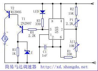
Simple motor speed governor
Published:2011/6/15 1:59:00 Author:TaoXi | Keyword: Simple, motor, speed governor
Related components (View)
View full Circuit Diagram | Comments | Reading(1749)
Voltage / current conversion circuit composed of MPY634
Published:2011/7/5 6:44:00 Author:Lucas | Keyword: Voltage / current conversion

MPY634 is an analog multiplier with the output current being proportional to the product of two input signals X and Y (both AC and DC) . When the input is AC signal, it needs to use isolation transformer, which is not shown in the figure. Taking into account MPY634 computing precision, the maximum of output current is 5mA. Therefore, the output voltage U. Peak - peak value is lOV, the minimum of Rs is 2kΩ.
(View)
View full Circuit Diagram | Comments | Reading(1670)
555 home appliance dual-purpose timer circuit
Published:2011/6/13 20:25:00 Author:TaoXi | Keyword: 555, home appliance, dual-purpose, timer
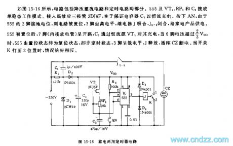
As the figure 15-16 shows, the circuit is composed of the step-down rectifier circuit and the timing circuit. The monostable operating mode is composed of the 555, VT1, RP1 and C3. You can add the field-effect transistor 3DJ6F to ensure the capacitor C3 is charged with the constant-current. If you press AN, the circuit is set because the pin-2 of 555 connects with the ground potential, pin-3 has the high electrical level, the relay J and J1-1 close to supply power to the home appliances.
After the 555 is set, the pin-7 is in the opening circuit state, C3 charges pin-7 through the constant current source VT1, when pin-6's voltage is higher than 2/3VDD, the 555 is from the set state to the reset state.
(View)
View full Circuit Diagram | Comments | Reading(823)
Voltage / current conversion circuit composed of INA105
Published:2011/7/5 6:39:00 Author:Lucas | Keyword: Voltage / current conversion

It can switch ±10V control voltage into ±lOμA tiny current. This circuit is used as small ion-current generator for chemical reaction. In the circuit, using A2 chip with resistor A1 (INA105) and low bias current operational amplifier A2 (OPA124) inside allows conversion accuracy in 0.1%. Output current prescribed minimum is decided by leakage current from the PCB and the ratio of the required output signal current and noise current. Accessing capacitor Cl can make effective value of noise circuit reduce from 317nA to 3.9 nA.
(View)
View full Circuit Diagram | Comments | Reading(708)
Simple artificial intelligence temperature control circuit
Published:2011/6/13 20:28:00 Author:TaoXi | Keyword: Simple, artificial intelligence, temperature control

This circuit uses the LM35 voltage type integrated temperature sensor, so that the circuit becomes very simple.
The LM35 is designed as one kind of internal circuit integrated temperature sensor which has been corrected, the output voltage is proportional to the celsius temperature, the linearity is good and the sensitivity is high, also it has the moderate precision, the output sensitivity is 10.0MV/℃, the precision is 0.5℃. The measurement range is -55 to +150℃. In the stationary temperature, the self-heating effect is low (0.08℃). The operating voltage is wide, and it can work in the power supply voltage of 4 to 20V with less consumption, the operating current is less than 60 uA. The output impedance is low, when the load is 1MA, the output impedance is 0.1Ω. (View)
View full Circuit Diagram | Comments | Reading(1825)
Sine wave converter circuit
Published:2011/7/5 8:04:00 Author:Lucas | Keyword: Sine wave converter

The circuit can be used as the signal source of calibration level meter or sensor-driven differential transformer. Circuit oscillation frequency is determined by the 74HCO4, and it is transferred lkHz by R. The supply voltage of Tl changes with the amplitude output. The switch turns the output voltage into square wave, then it will get sine wave by filtering the high frequency by low-pass filter. Waveform distortion depends on the performance of the filter, and the series of filter is used according to the need.
(View)
View full Circuit Diagram | Comments | Reading(2072)
Temperature/voltage conversion circuit of thermistor
Published:2011/7/5 7:57:00 Author:Lucas | Keyword: Temperature/voltage conversion, thermistor


In the circuit shown in Figure 1-52 (a), Rl and thermistor RT are connected in parallel, and its role is to improve the linear relationship between the thermal resistor and temperature changing. RT and R1-R5 form a bridge with the bridge arm resistance in lOkΩ. Adjusting RP1 could keep the bridge balance, so that the output voltage is equal to zero at the required temperature. Output voltage U. is decided by the thermistor constant B and the voltage applied on bridge. Figure 1-52 (b) shows the circuit with the output voltage sensitivity in 1OmV / ℃, temperature measurement range in -50 +15 O ℃. When the bridge is added +5 V reference voltage U (REF), the thermistor RT will flow a constant current.
(View)
View full Circuit Diagram | Comments | Reading(4857)
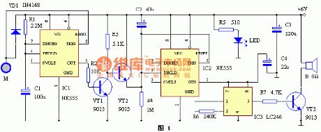
555 reading-newsstand automatic floodlight circuit
Published:2011/6/13 20:25:00 Author:TaoXi | Keyword: NE555, automatic, floodlight

As the figure 17-25 shows, the automatic floodlight circuit is composed of the optoelectronic multiplex switch circuit, the oscillation clock generator and the timer control circuit.etc.
The 555 offset voltage network is composed of the photodetector and the RP1. In the daytime, the photodetector has the low resistance, the electric potential of 555's pin-5 is higher than 2/3VDD threshold level, the circuit resets, pin-3 has the low level voltage, J failure to actuate, At night, the photodetector has the high resistance, pin-2's electrical level is lower than 1/3VDD, 555 sets, pin-3 has high level voltage, J closes and the light turns on.
The timing power-off circuit is composed of the IC2~IC4 and the VT. The ultra-low frequency astable multivibrator is composed of the IC2(555) and R3,R4,R5.
(View)
View full Circuit Diagram | Comments | Reading(552)
555 water temperature alarm circuit
Published:2011/6/13 20:26:00 Author:TaoXi | Keyword: 555, water temperature, alarm circuit
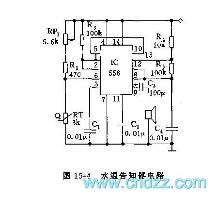
As the figure 15-4 shows, this circuit uses the 556 as the core. The monostable trigger is composed of the left part (1/2 556) of IC, the R1, R3, RP1 and the thermistor probe. The thermistor uses the resistance which has the RT=3kΩ and the negative temperature coefficient. When the water temperature is 100 degrees celsius, the resistance value is about 240Ω; when the water temperature is 50 degrees celsius, the resistance value is about 950Ω. If you pre-set the temperature and adjust RP1 to 50Ω, so the VA=RT/(RP1+R1+RT)<1/3, when the trigger port pin-6's electric potential is lower than 1/3VDD, the trigger is set, the high electrical level which is output by the pin-5 adds to the right part of the 1/2 556's reset port, f=1.44/(R4+2R5)C4, the oscillation frequency is about 1000Hz.
(View)
View full Circuit Diagram | Comments | Reading(1126)
Balance constant current output circuit
Published:2011/7/5 7:48:00 Author:Lucas | Keyword: Balance , constant current output


When the circuit has the external 0-10V voltage, you can choose a wide range of current, which is used as the part of the circuit of function generator, waveform generator. Al and A2 are the differential output circuit, which can change the unipolar input into a good balance circuit, and it can be used to change the 0-lOV input voltage into a 0-1mA output current. If Rl = R2, then the two ends of Rl, R2 will generat the same voltage, that is . It requires to generate the asymmetric waveform, so thatit need. It can also be used to generate a sawtooth waveform.
(View)
View full Circuit Diagram | Comments | Reading(2395)
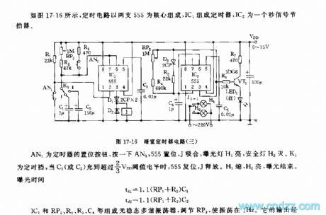
The 555 darkroom timer circuit (3)
Published:2011/6/14 2:44:00 Author:TaoXi | Keyword: darkroom, timer
Related components PDF download:
NE5553DG6
As the figure 17-16 shows, the timer circuit uses two 555 as the core, the timer is composed of the IC1, IC2 is the
second signal metronome.
AN1 is the timer's set button, if you press AN1, the 555 sets, the J closes, the exposure light H1 turns on and the safe light H2 turns off. K1 is the timing gear, when C1 or C2 has the voltage level of more than 2/3VDD, 555 resets, J releases. H1 turns off, H2 turns on, the exposure is over.
The exposure time: td1=1.1(RP1+R2)C1 td2=1.1(RP1+R2)C2
The astable multivibrator is composed of the IC2, RP2,R4,R5 and the C4.etc, By adjusting RP2, you can make the oscillation in the 1Hz. It's output drives the red LED to turn on through VT1.
(View)
View full Circuit Diagram | Comments | Reading(499)
AC current / voltage conversion circuit
Published:2011/7/5 7:36:00 Author:Lucas | Keyword: AC , current / voltage conversion

The circuit uses CT current converter, and the first level of flows the measured current, then the secondary level could get the AC voltage being proportional to the input current. When the measured AC current wire crosses the ring core CT, due to the magnetic field changes generate inducing voltage on the two ends of coil, and the higher current frequency will result higher induced voltage. Low-frequency characteristics of coil depends on the load resistors R1 and RP1, RP2, which are used to adjust the switching sensitivity. If using RP1 and RP2 to do interaction adjustment, it will make the circuit have flat frequency characteristics.
(View)
View full Circuit Diagram | Comments | Reading(7301)
The reinforced bass metronome circuit composed of the CD4017
Published:2011/6/14 2:44:00 Author:TaoXi | Keyword: reinforced bass metronome

The bass metronome can reinforce each beat, and it can increase the bass intensities of 2, 3, 4, 6 and 9. This metronomehas thelight display function by using the red LED and green LED, the red LED is used as the lighting instruction of the reinforced bass beat, and the non-reinforced bass beat is instructed by the green LED, so the user can identify which one is the reinforced bass beat easily. The reinforced bass metronome circuit is as shown in the figure. The whole circuit is composed of four CMOS digital integrated circuits. (View)
View full Circuit Diagram | Comments | Reading(1309)
Door alarm circuit with the time recognition function composed of the NE555
Published:2011/6/14 2:45:00 Author:TaoXi | Keyword: Door alarm, time recognition
Door alarm circuit with the time recognition function (View)
View full Circuit Diagram | Comments | Reading(519)
Triangle / sine wave converter circuit
Published:2011/7/5 7:08:00 Author:Lucas | Keyword: Triangle / sine wave converter

This is the approximate polygonal circuit, which could change the sine wave in triangular wave, and it is widely used in the sine function generator. In the circuit, VTl-VT4 are used as power circuit of VD6, VDl2, and the voltage changes with temperature, then V is available as a sensor to detect the ambient temperature. RP1 and RP2 could adjust the positive and negative voltage. For reducing distortion, they should be interactive adjusted to make high-order harmonic distortion in 0.2% to 0.5% . VT5 and VT6 are the push-pull buffer amplifiers with the load impedance in lkΩ. For driving 500 load, it should be added the broadband amplifier with four times gain.
(View)
View full Circuit Diagram | Comments | Reading(7510)
555 automatic water supply circuit with the magnetic card to get water
Published:2011/6/13 20:27:00 Author:TaoXi | Keyword: 555, automatic, water supply circuit, magnetic card
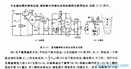
This circuit is composed of the step-down rectifier circuit, the magnetic control trigger and relay control electromagnetic valve circuit.etc, as the figure 15-41 shows.
The HG is the reed pipe magnetic control switch, it is usually in the disconnected state, the monostable delay circuit is composed of the HG, 555, RP1, R2 and C2, the charging voltage (>2/3VDD) of C2 makes the 555 in the reset state, the relay K will not work. If the user put the magnetic card into the entrance, when the magnetic card gets through the reed pipe HG, the contact point closes, the pin-2's low electrical level of the 555 sets the 555, the pin-3 has the high electric potential, the relay K gets power to close, the contact point K1-1 closes too, the electromagnetic valve DF opens to prevent the water.
(View)
View full Circuit Diagram | Comments | Reading(726)
| Pages:1612/2234 At 2016011602160316041605160616071608160916101611161216131614161516161617161816191620Under 20 |
Circuit Categories
power supply circuit
Amplifier Circuit
Basic Circuit
LED and Light Circuit
Sensor Circuit
Signal Processing
Electrical Equipment Circuit
Control Circuit
Remote Control Circuit
A/D-D/A Converter Circuit
Audio Circuit
Measuring and Test Circuit
Communication Circuit
Computer-Related Circuit
555 Circuit
Automotive Circuit
Repairing Circuit