
Circuit Diagram
Index 1606
The audio control circuit
Published:2011/7/6 4:39:00 Author:qqtang | Keyword: audio control

View full Circuit Diagram | Comments | Reading(809)
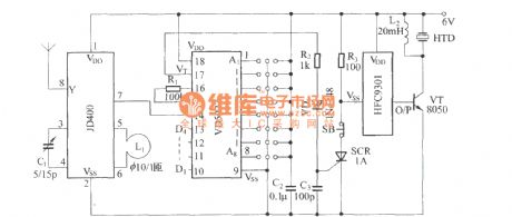
The 51 watchdog circuit
Published:2011/7/6 4:36:00 Author:qqtang | Keyword: watchdog circuit
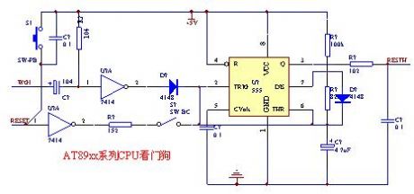
The feed interval of the circuit is less than 3S, the feeding pulse is higher than 5uS, usually, the intermittent pins or pins with period signal keys can be used, just don't affect the former functions.
(View)
View full Circuit Diagram | Comments | Reading(634)
The 4-word control keypad circuit
Published:2011/7/6 4:38:00 Author:qqtang | Keyword: control keypad

The Keypad must be the kind with a common terminal and a separate connection for each key. On a 12-key pad, look for 13 terminals. The matrix type with 7 terminals will NOT do. The Alarm is set by pressing a single key. Choose the key you want to use and wire it to 'E'. Choose the four keys you want to use to switch the alarm off, and connect them to 'A B C & D'. Your code can include the non-numeric symbols. With a 12-key pad, over 10 000 different codes are available. Wire the common to R1 and all the remaining keys to 'F'. When 'E' is pressed, current through D2 and R9 switches Q5 on. The relay energises, and then holds itself on by providing base current for Q5 through R10. The 12-volt output is switched from the off to the set terminal, and the LED lights. To switch the Alarm off again it is necessary to press A, B, C & D in the right order. The IC is a quad 2-input AND gate, a Cmos 4081. These gates only produce a high output when both inputs are high. Pin 1 is held high by R5. This 'enables' gate 1, so that when 'A' is pressed, the output at pin 3 will go high. This output does two jobs. It locks itself high using R2 and it enables gate 2 by taking pin 5 high. The remaining gates operate in the same way, each locking itself on through a resistor and enabling its successor. If the correct code is entered, pin 10 will switch Q4 on and so connect the base of Q5 to ground. This causes Q5 to switch off and the relay to drop out. Any keys not wired to 'A B C D or E' are connected to the base of Q3 by R7. Whenever one of these 'wrong' keys is pressed, Q3 takes pin 1 low. This removes the 'enable' from gate 1. (View)
View full Circuit Diagram | Comments | Reading(532)
The 6v,2W alarming flash lamp circuit
Published:2011/7/6 4:52:00 Author:qqtang | Keyword: alarming flash lamp
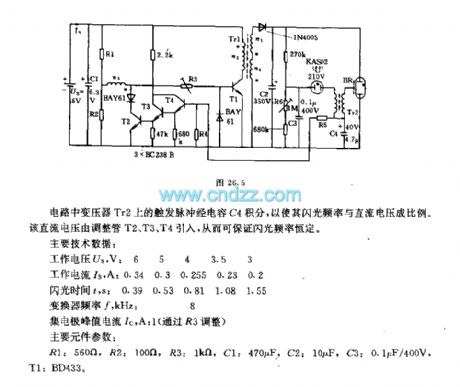
In the circuit, the trigger pulses on the transformer Tr2 are integrated by the capacitor C, so the flash frequency is in proportion to the DC voltage. The DC voltage is imported by the regulators of T2, T3 and T4, so the flash frequency is sure to be constant.Main technology data:Working voltage Us, V: 6 5 4 3.5 3Working current Is, A: 0.34 0.3 0.255 0.23 0.2 Flashing time t, s: 0.39 0.53 0.81 1.08 1.55The converter frequency f, KHz: 8The collecting electrode peak current Ic, A: 1 (regulated by R3) Main element parameters:R1: 560Ω, R2:100Ω R3: 1KΩ C1:470μF, C2: 10μF, C3:0.1μF/400V, T1: BD433. (View)
View full Circuit Diagram | Comments | Reading(693)
The 5G0602 special alarm integrated application circuit
Published:2011/7/6 9:30:00 Author:qqtang | Keyword: special alarm, application circuit

The 5G0602 special alarm integrated application circuitIn the figure, the sensor is a light sensitive tube, by replacing it with a thermistor, the circuit will be a temperature alarm circuit. In accordance with this law, 5G0602 can compose all kinds of alarms. (View)
View full Circuit Diagram | Comments | Reading(480)
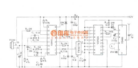
The PIC single chip machine control burglarproof alarm circuit
Published:2011/7/6 4:30:00 Author:qqtang | Keyword: single chip machine, burglarproof alarm


VD5026, T4 and so on in Figure 1 compose the remote control emitting unit. One line of the 12V power supply is directly provided for the high-frequency emitting circuit, the other line gets a 5V or so voltage after the distribution of D10 and R24~R27 when the keys of K1~K4 are pressed, and the voltage is then offered to VD5026 by D6~D9. When one of the emitting keys K1~K2 is pressed, the pin is outputting the encoding pulse bundle, which is launched by T4 after modulation(the frequency of the high-frequency oscillator composed of T4 is about 180MHz). (View)
View full Circuit Diagram | Comments | Reading(750)
The SX-6 human body inducting switch application circuit
Published:2011/7/6 3:03:00 Author:qqtang | Keyword: human body, inducting switch
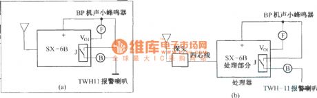
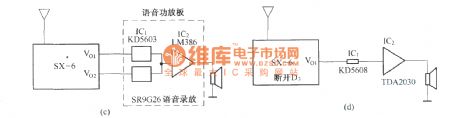
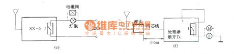
In figure (a) is the radar alarm composed of the SX-6 human body inducting switch; In figure (b) is the radar alarm whose probe and host are divided; In figure (c) is the auto audio device composed of the SX-6 human body inducting switch; In figure (d) is the electric dog circuit composed of the SX-6 human body inducting switch; In figure (e) is the energy-saving auto switch circuit composed of the SX-6 human body inducting switch; In figure (f) is the fast reaction alarm composed of the SX-6 human body inducting switch. (View)
View full Circuit Diagram | Comments | Reading(560)
Zone Alarm System
Published:2011/7/6 1:22:00 Author:qqtang | Keyword: Alarm System

This is a complete alarm system with 5 independent zones suitable for a small office or home environment. It uses just 3 CMOS IC's and features a timed entry / exit zone, 4 immediate zones and a panic button. There are indicators for each zone a system armed indicator. The schematic is as follows:Each zone uses a normally closed contact. These can be micro switches or standard alarm contacts (usually reed switches). Zone 1 is a timed zone which must be used as the entry and exit point of the building. Zones 2 - 5 are immediate zones, which will trigger the alarm with no delay. Some RF immunity is provided for long wiring runs by the input capacitors, C1-C5. C7 and R14 also form a transient suppresser. The key switch acts as the Set/Unset and Reset switch. For good security this should be the metal type with a key. At switch on, C6 will charge via R11, this acts as the exit delay and is set to around 30 seconds. This can be altered by varying either C6 or R11. Once the timing period has elapsed, LED6 will light, meaning the system is armed. LED6 may be mounted externally (at the bell box for example) and provides visual indication that the system has set. Once set any contact that opens will trigger the alarm, including Zone 1. To prevent triggering the alarm on entry to the building, the concealed re-entry switch must be operated. This will discharge C6 and start the entry timer. The re-entry switch could be a concealed reed switch, located anywhere in a door frame, but invisible to the eye. The panic switch, when pressed, will trigger the alarm when set. Relay contacts RLA1 provide the latch, RLA2 operate the siren or buzzer. (View)
View full Circuit Diagram | Comments | Reading(544)
The simple leakage alarm circuit
Published:2011/7/6 9:54:00 Author:qqtang | Keyword: leakage alarm
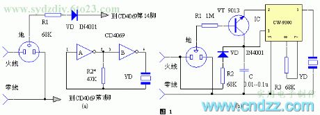
Element selection and producingThe elements are chosen as the principle diagram While making it, we can choose a circuit according to the concrete condition, the 2 electrodes in the 2-hole outlet in the mixed outlet are cut off, so the circuit elements can be accommodated, and the installation is done in the room. After the installation, we can simulate the leakage dial with a 200Ω, one of whose terminals is connected with the power supply wire, while the other terminal is connected with the ground terminal, the circuit is only needed to work normally. In the figure, the withstand voltage of the diode should be higher than 400V, YD can be the Φ27mm, βof the transistor VT is ≥100, and the powers of all the resistors are 1/8W. (View)
View full Circuit Diagram | Comments | Reading(495)
The fire monitoring wireless alarm circuit
Published:2011/7/6 9:38:00 Author:qqtang | Keyword: fire monitoring, wireless alarm

(a) is the alarm emitting circuit;
(b) is the alarm reception circuit. (View)
View full Circuit Diagram | Comments | Reading(678)
The limit temperature exceeding alarm
Published:2011/7/6 9:34:00 Author:qqtang | Keyword: limit temperature, exceeding alarm

(a) is the alarm emitting circuit;
(b) is the alarm reception circuit. (View)
View full Circuit Diagram | Comments | Reading(512)
The domestic wireless burglarproof alarm circuit
Published:2011/7/6 9:04:00 Author:qqtang | Keyword: wireless burglarproof alarm


The circuit principle1. The invasion detector and micro alarm emitterIn figure 1 is the principle diagram of the invasion detector and the micro alarm emitter. The small magnet and the reed pipe E of normally closed contactor compose the invasion detector, the small magnet is fixed at the door leaf of the storeroom, the reed pipe E, which is close to the magnet, is installed on the corresponding door frame. Usually, the door is closed, as the magnet is close to E, so the 2 normally closed contators in E is switched off because of the external effect, and the micro emitter is not working without power.
(View)
View full Circuit Diagram | Comments | Reading(611)
The language circuit of ND-1 vibration moving sensor
Published:2011/7/6 2:01:00 Author:qqtang | Keyword: language circuit, moving sensor
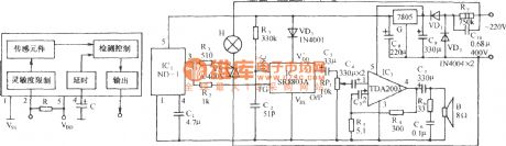
The circuit is shown in the figure, which consists of the vibration moving sensor, SCR light circuit, language sound making circuit, audio power amplifier circuit and AC step-down rectifier circuit,etc. It can be widely used in home burglarproof doors, safety boxes, vehicles, motorcycles, domestic appliances and so on. When the things are stolen or the windows/doors are pried, it will launch the sound of catch the thief . The IC is the ND-1 vibration moving sensor, which is full-direction sensing element mixing the vibration detection and the moving detection. (View)
View full Circuit Diagram | Comments | Reading(668)
The domestic burglarproof alarm
Published:2011/7/6 4:57:00 Author:qqtang | Keyword: domestic burglarproof alarm
Emitting circuit:
Receiving circuit:
(View)
View full Circuit Diagram | Comments | Reading(525)
The burglarproof alarm circuit
Published:2011/7/6 9:22:00 Author:qqtang | Keyword: burglarproof alarm
This circuit is used as the alarm of the vehicle and home, it is a dual time-based integrated circuit TDB0556, in which the first time-based circuit is a dual steady multiple oscillator, the circuit is getting into work after the switch S is pressed. Because of the voltage on the threshold input terminal 2, the output 5 is in a zero LEV. The second time-based circuit is in the output terminal locked state due to the zero state of 8-pin and 12-pin. The capacitor C1 is discharging. Once the door contactor or the briefcase contactor is closed, the alarm signal is emitted.
(View)
View full Circuit Diagram | Comments | Reading(658)
The ultra-short wave package left reminding alarm circuit
Published:2011/7/6 2:14:00 Author:qqtang | Keyword: ultra-short wave, package left reminding alarm
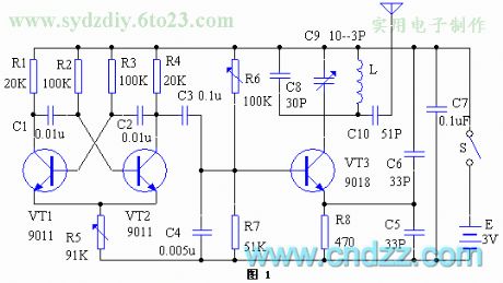

The device consists of the emitter and receiver, which works in the FM wave. The principle of the emitter in shown in the figure, which is a multi-oscillator composed of the triodes (VT1 and VT3) and external components, the working frequency is 1000Hz, and the signal is picked out by C3, and modulated by the FM oscillator composed of VT3 and LC components, the modulated signal is output by C10, and emitted to the sky by the internal micro aerial, of which the function of C6 is to broaden the frequency band and avoid the human inducting effect on the frequency.
(View)
View full Circuit Diagram | Comments | Reading(580)
The multi-functional portable dual-way alarm circuit
Published:2011/7/6 8:47:00 Author:qqtang | Keyword: multi-functional, portable, dual-way alarm

This circuit consists of two parts, the upper limit alarm function is composed of A, B, R4 and C1, and C, D, R5 and C2 form the lower limit alarm function, see as figure 1. Usually, there are two alarm spots, the upper and lower, which are fixed in RP1 and RP2 respectively, which make the input terminals of A and C both in a high LEV, and both of them output a low LEV so the oscillators stop. When it is too hot outside, the resistance of the thermistor is falling down, which makes A output a high LEV, B is starting to oscillate, and the piezoelectric pottery chip YD is generating the bumming sound of high frequency. At the same time, LED1 is glowing, indicating that the temperature is too high. (View)
View full Circuit Diagram | Comments | Reading(560)
The multi-functional remote alarm controller circuit
Published:2011/7/6 4:54:00 Author:qqtang | Keyword: multi-functional, remote, alarm controller

View full Circuit Diagram | Comments | Reading(591)
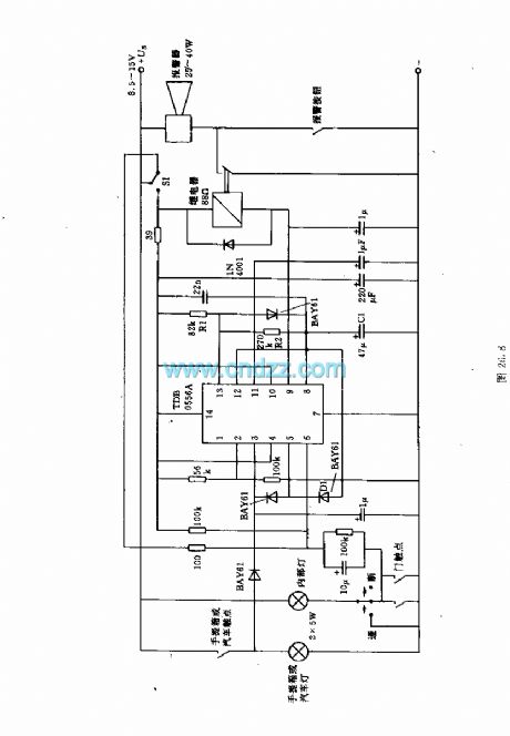
The electric lock circuit of Guanghua burglarproof door bell
Published:2011/7/6 10:01:00 Author:qqtang | Keyword: electric lock, door bell

See as the figure, the circuit consists of the door control magnetic switch, the relay control circuit, ding-dong door bell sound making circuit, the simulated police car sound circuit and so on. It can be the door bell, or used as the burglarproof alarm of pry. (View)
View full Circuit Diagram | Comments | Reading(701)
The light sensitive high power fire alarm circuit (LM1801)
Published:2011/7/6 10:09:00 Author:qqtang | Keyword: light sensitive, high power, fire alarm

See as the figure, the circuit consists of the light sensitive detecting bridge, the fog specialized control magnetic valve water spray circuit, the simulated sound and audio amplifier circuit, the AC step-down rectifier circuit and so on. (View)
View full Circuit Diagram | Comments | Reading(1092)
| Pages:1606/2234 At 2016011602160316041605160616071608160916101611161216131614161516161617161816191620Under 20 |
Circuit Categories
power supply circuit
Amplifier Circuit
Basic Circuit
LED and Light Circuit
Sensor Circuit
Signal Processing
Electrical Equipment Circuit
Control Circuit
Remote Control Circuit
A/D-D/A Converter Circuit
Audio Circuit
Measuring and Test Circuit
Communication Circuit
Computer-Related Circuit
555 Circuit
Automotive Circuit
Repairing Circuit