
Circuit Diagram
Index 1608
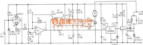
The language calling circuit of combustible gas leakage
Published:2011/7/5 20:56:00 Author:Borg | Keyword: language calling circuit, combustible gas leakage

See as the circuit in the figure, it consists of the gas sensor, language generating circuit and AC step-down rectifier circuit, etc. (View)
View full Circuit Diagram | Comments | Reading(647)
The auto ventilation and language circuit of harmful gas exceeding in the combustible gas bathroom
Published:2011/7/5 20:52:00 Author:Borg | Keyword: auto ventilation, language reminding circuit,
View full Circuit Diagram | Comments | Reading(445)
The self-coupled step-down starting circuit of avoid main contactor wielding accidents
Published:2011/7/5 20:47:00 Author:Borg | Keyword: self-coupled, step-down, wielding accidents

In the circuit, the additional mixed contactors of KM1 and KM2 and the time delay contactor of KT are serially connected as a OR logic circuit. When it is the starting time, KT is taking action, the KM1 and KM2 coil circuit are cut off, KM1 and KM2 additional contactors are reset. Meanwhile, if the main contactors of KM1 and KM2 are wielded, the contactors which are cut off by KM1 and KM2 can cut off the current that cross the transformer coil, so the accident of serious heat or break of TA duo to contactor wielding can be avoided. (View)
View full Circuit Diagram | Comments | Reading(1851)
The frequency speed circuit with a remote control box
Published:2011/7/5 20:36:00 Author:Borg | Keyword: frequency speed circuit, remote control box

In the circuit , FR-FK is a remote control box. When the converter can't be operated due to the environment or the environment protection condition, or it can't be centrally controlled, this circuit can be used to solve these problems. The remote control box(module) connects with 3 external keys (acceleration, deceleration and offset) and a starting switch. When it is operated, the switch is closed first, and other keys are pressed according to need. The terminals of M1 and M2 of FR-FK are connected with the frequency counter, whose 2-pin and 5-pin are linked with the 2-pin and 5-pin of the converter shielding line. (View)
View full Circuit Diagram | Comments | Reading(511)
The alarm control key circuit
Published:2011/7/6 1:03:00 Author:Borg | Keyword: alarm, control key

This switch will suit the Modular Burglar Alarm circuit. However, it also has other applications. The Keypad must be the kind with a common terminal and a separate connection for each key. On a 12-key pad, look for 13 terminals. The matrix type with 7 terminals will NOT do. Choose the five keys you want as your code, and connect them to 'A, B, C, D & E'. Wire the common to R1 and all the remaining keys to 'F'. Because your choice can include the non-numeric symbols, almost 100 000 different codes are available. The Alarm is set using the first four of your five chosen keys. When 'A, B, C & D' are pressed in the right order and within the time set by C1 and R2 (about 10 seconds), current through R11 switches Q6 on. The relay energizes, and then holds itself on by providing base current for Q6 through R12. The 12-volt output switches from the off to the set terminal, and the LED lights. To switch the Alarm off again it is necessary to press A, B, C, D & E in the right order. The IC is a quad 2-input AND gate, a Cmos 4081. These gates only produce a high output when both inputs are high. Pressing 'A' takes pin 1 high for a period of time set by C1 and R2. This 'enables' gate 1, so that when 'B' is pressed, the output at pin 3 will go high. This output does two jobs. It locks itself high using R3 and it enables gate 2 by taking pin 5 high. The remaining gates operate in the same way, each locking itself on through a resistor and enabling its successor. If the correct code is entered within the time allowed, pin 10 will switch Q5 on and so connect the base of Q6 to ground. This causes Q6 to switch off and the relay to drop out. Any keys not wired to 'A, B, C, D or E ' are connected to the base of Q4 by R9. Whenever one of these 'wrong' keys is pressed, Q4 takes pin 1 low. This removes the 'enable' from gate 1, and the code entry process fails. If C, D or E is pressed out of sequence, Q1, Q2 or Q3 will also take pin 1 low, with the same result. You can change the code by altering the keypad connections. If you make a mistake entering the code, just start again. If you need a more secure code you can use a bigger keypad with more 'wrong' keys wired to 'F'. A 16-key pad gives over half a million different codes. All components are shown lying flat on the board; but some are actually mounted upright. The links are bare copper wires on the component side. Two of the links must be fitted before the IC. (View)
View full Circuit Diagram | Comments | Reading(549)
The doorphone communication circuit
Published:2011/7/6 0:59:00 Author:Borg | Keyword: doorphone, communication circuit

In this doorphone circuit,an 8 ohm speaker is used both as a microphone and also an output device. The BC109C stage amplifies in common base mode, giving good voltage gain , whilst providing a low impedance input to match the speaker. Self DC bias is used allowing for variations in transistor current gain. An LM386 is used in non-inverting mode as a power amplifier to boost voltage gain and drive the 8 ohm speaker. The 10k potentiometer acts as the volume control, and overall gain may be adjusted using the 5k preset. The double pole double throw switch, reverses the loudspeaker positions, so that one is used to talk and the other to listen. Manually operating the switch (from inside the house) allows two way communication. (View)
View full Circuit Diagram | Comments | Reading(705)
The ultra-sonic moving alarm
Published:2011/7/5 22:21:00 Author:qqtang | Keyword: ultra-sonic
View full Circuit Diagram | Comments | Reading(720)
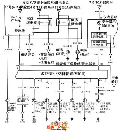
The Honda-Accord 2003 steering signal lamp circuit
Published:2011/7/6 1:09:00 Author:qqtang | Keyword: Honda-Accord, steering signal lamp

The Honda-Accord 2003 steering signal lamp circuit is shown as above.
(View)
View full Circuit Diagram | Comments | Reading(2221)
Accord 2003 safety alarm/remote start system circuit (2)
Published:2011/7/5 22:12:00 Author:qqtang | Keyword: safety alarm, remote start system
Accord 2003 safety alarm/remote start system circuit (2) is shown in the figure.
(View)
View full Circuit Diagram | Comments | Reading(623)
IR2156--The fluorescence lamp integrated electric ballast circuit
Published:2011/7/5 22:20:00 Author:qqtang | Keyword: fluorescence lamp, electric ballast circuit

IR2156 is the high-cost, high-benefit solution of the fluorescence lamp ballast, which integrates the programmable working frequency, which can pre-heat, light lamp and keep the ballast work, the ballast and lamp fault protection.
Figure: IR2156--The fluorescence lamp integrated electric ballast circuit (View)
View full Circuit Diagram | Comments | Reading(1837)
The electric ballast control ML4831 circuit of high power factor and high efficiency
Published:2011/7/5 22:10:00 Author:qqtang | Keyword: ballast control, high power factor

Figure:The electric ballast control ML4831 of high power factor and high efficiency (View)
View full Circuit Diagram | Comments | Reading(507)
Line-Output Transformer Short-Circuit Detection Circuit Diagram
Published:2011/7/4 10:06:00 Author:Vicky | Keyword: Line-OutputTransformer, Short-Circuit Detection
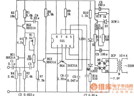
As part of the line-output transformer short-cut detection circuit, dropout pulse is composed of 555, BG4, C6, and R9 etc. When the transformer works normally, the timing cycle of monostable timing circuit which is made of 555, R9 and C6 is longer than the cycle of input trigger pulse. Therefore, under continuous triggering, pin 3 of 555 presents high level (about +5V) continuously, luminous diode LED2 (green) is lighted to the line-out transformer works well without short circuit or punch-through. If there is short circuit of punch-through, then because of mutual-inductor among the transformer windings, the transformer presents low impedance, high-damping, and the oscillator stops working. The correspondent 555 gives out low level through pin ③ for pin ② cannot receive trigger signal. Then the luminous diode LED1 (red) is lightened to indicate the abnormality of the transformer. (View)
View full Circuit Diagram | Comments | Reading(1685)
The strain meter circuit of the internal half-bridge net of the signal modulator
Published:2011/7/6 1:05:00 Author:qqtang | Keyword: strain meter, half-bridge net, signal modulator
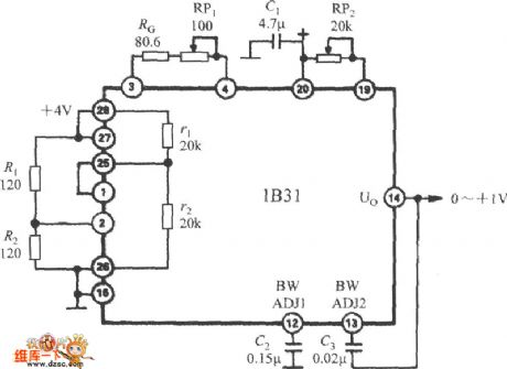
The the strain meter circuit of the internal half-bridge net of the wide band stress signal modulator 1B31 is shown as above.
(View)
View full Circuit Diagram | Comments | Reading(635)
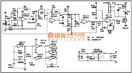
Electric single-girder crane radio remote controller TX315B1
Published:2011/6/14 2:53:00 Author:TaoXi | Keyword: Electric, single-girder crane, radio remote controller
The right part of the dotted line is the original operating circuit of the crane, K1~K4 are the original manual operating buttons, now you can use the relay's contact point to replace it, SQ is the limit ascending switch. KM1~KM4 are the communication relays, and they can be used to control the ascending motor M1 and the traveling motor M2's reversal and positive-turning to realize the gourd walking and the goods lifting. The left part of the dotted line is the new wireless remote control circuit. In the circuit, the four output port A~D of the TX315B1 receiving circuit can drive the DC relays K1 ~ K4 through the drive tube VT ~ VT4.
(View)
View full Circuit Diagram | Comments | Reading(964)
Wireless remote control/touch dimmer circuit RCM1A/RCM1B
Published:2011/6/14 2:55:00 Author:TaoXi | Keyword: Wireless remote control, touch dimmer circuit
The wireless remote control/touch dimmer circuit is designed as one kind of incandescent lamp dimmer switch that is composed of the radio remote control components RCM1A/RCM1B and the CS7232 touch dimmer integrated circuit, and it can be used to control the pendant lamp, table lamp and wall lamp.etc, also it has the features of exquisite size, easy to use and good stability and reliability. CS7232 is designed as one kind of CMOS type integrated circuit that can be used in the incandescent light control, it controls the lamp brightness through controlling the bidirectional thyristor conduction angles, and it has the features of low power consumption, multi-function and high control sensitivity, and it can be used in the incandescent lamp circuit which supplies power to the AC 220/115V, 50/60Hz power supply.
The CS7232 is in the DIP 8 pins plastic package, the pin functions and the internal circuit block diagram is as shown:
(View)
View full Circuit Diagram | Comments | Reading(1007)
The children anti-lost reminder transceiver module composed of the RCMlA/RCMlB
Published:2011/6/14 2:56:00 Author:TaoXi | Keyword: children, anti-lost reminder, transceiver module
This circuit is composed of the transmitter and receiver, the core components are the RCM1A and RCM1B.
(View)
View full Circuit Diagram | Comments | Reading(624)
Six-channel remote control receiver circuit CS902
Published:2011/6/14 2:57:00 Author:TaoXi | Keyword: Six-channel, remote control receiver
The key components datathat will be used in this article:
CS902 CS906 SM5272-L6
(View)
View full Circuit Diagram | Comments | Reading(661)
The oxygen concentrator circuit
Published:2011/6/13 21:57:00 Author:Seven | Keyword: oxygen inhaler

View full Circuit Diagram | Comments | Reading(4205)
ground isolation circuit by optical couplers
Published:2011/7/4 23:44:00 Author:chopper | Keyword: ground isolation, optical couplers
As for some circuits,one point connection between AGND and DGND is very different.Additionally,because of the difference of electric potential of the AGND and DGND in the circuit,the landlines can't be connected.And we adopts optical coupler to separate the AGND and DGND,just as picture.If the signal is transfered in the form of light,then the connection between AGND and DGND is not necessary.
(View)
View full Circuit Diagram | Comments | Reading(496)
The circuit of the oxygen inhaler
Published:2011/6/13 21:57:00 Author:Seven | Keyword: oxygen inhaler

View full Circuit Diagram | Comments | Reading(703)
| Pages:1608/2234 At 2016011602160316041605160616071608160916101611161216131614161516161617161816191620Under 20 |
Circuit Categories
power supply circuit
Amplifier Circuit
Basic Circuit
LED and Light Circuit
Sensor Circuit
Signal Processing
Electrical Equipment Circuit
Control Circuit
Remote Control Circuit
A/D-D/A Converter Circuit
Audio Circuit
Measuring and Test Circuit
Communication Circuit
Computer-Related Circuit
555 Circuit
Automotive Circuit
Repairing Circuit