
Circuit Diagram
Index 1617
Power failure emergency lamp circuit(3)
Published:2011/7/4 22:50:00 Author:zj | Keyword: Power failure, emergency lamp circuit

View full Circuit Diagram | Comments | Reading(679)
Power failure emergency lamp circuit(4)
Published:2011/7/4 22:48:00 Author:zj | Keyword: Power failure, emergency lamp circuit

View full Circuit Diagram | Comments | Reading(716)
The remote control lock alarm(TH151A/B, the vibration sensor T968)
Published:2011/7/4 20:31:00 Author:Borg | Keyword: remote control, lock alarm

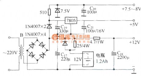
This circuit consists of the burglarproof host, door magnet trigger switch, vibration sensing switch, electric control lock with keys, battery that doesn't need maintenance and AC power supply, etc.Hose circuit:
Power supply circuit:
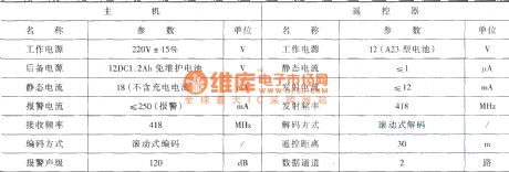
The working parameters of the hose and remote control:
(View)
View full Circuit Diagram | Comments | Reading(671)
The invade break-down caller circuit of the balcony door/window
Published:2011/7/4 20:52:00 Author:Borg | Keyword: invade, caller, balcony door/window
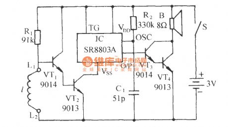
See as the figure, the circuit consists of the electric switch and language sound generating circuit, two parts in total. When the alarm line 1 of the balcony is broken down by the invader, it will generate the hurried calling sound immediately. (View)
View full Circuit Diagram | Comments | Reading(643)
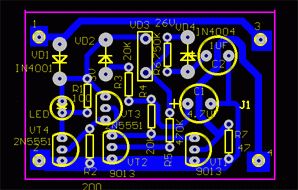
The small and contactless fridge time delay protector circuit
Published:2011/7/4 21:05:00 Author:Borg | Keyword: contactless fridge, time delay protector

The small and contactless fridge time delay protector The contactless fridge has a few elements, and it's low-cost, small-size and without debugging, of which the dual-way SCR replaces the relay.Working principle The protector circuit is shown in the figure. The 220V AC current is stepped down by capacitor C1, half-rectified by VD1, regulated by VDW, and then sent to the time-based circuit 555 as the working power supply, the time of getting through is 5 min, the output terminal of 3-pin of the time-based circuit is shifted from low LEV to high LEV, the dual-way SCR VS is conducting and getting into work, which powers the fridge. At the moment, the LED is glowing, which means the power supply is normal.
(View)
View full Circuit Diagram | Comments | Reading(1264)
Electronic flykilling device circuit
Published:2011/7/5 20:58:00 Author:Christina | Keyword: Electronic, flykilling device

This electronic flykilling device is very simple and effective .
(View)
View full Circuit Diagram | Comments | Reading(626)
ChangFeng LieBao SUV air conditioning system (single) circuit
Published:2011/7/5 20:48:00 Author:Christina | Keyword: ChangFeng, LieBao, SUV, air conditioning system
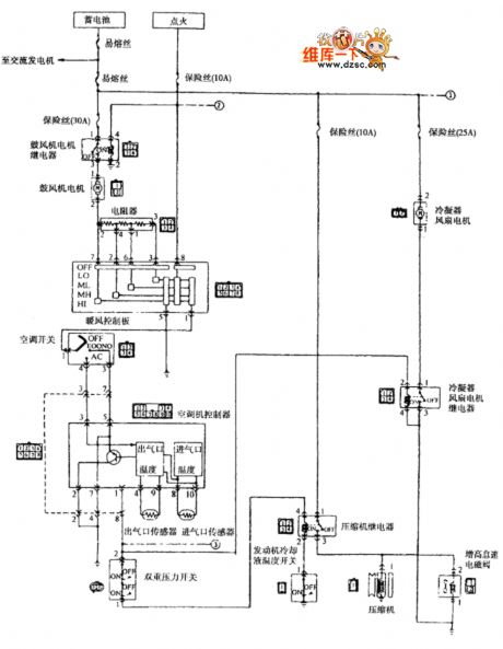
The ChangFeng LieBao SUV air conditioning system (single) circuit is as shown in the figure:
(View)
View full Circuit Diagram | Comments | Reading(449)
ChangFeng LieBao SUV air conditioning system (double) circuit
Published:2011/7/5 20:45:00 Author:Christina | Keyword: ChangFeng, LieBao, SUV, air conditioning system
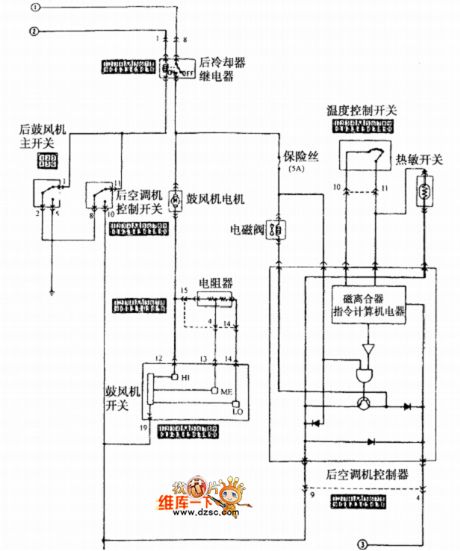
The ChangFeng LieBao SUV air conditioning system (double) circuit is as shown in the figure:
(View)
View full Circuit Diagram | Comments | Reading(472)
ND838 typical application circuit
Published:2011/7/5 20:43:00 Author:Christina | Keyword: typical application
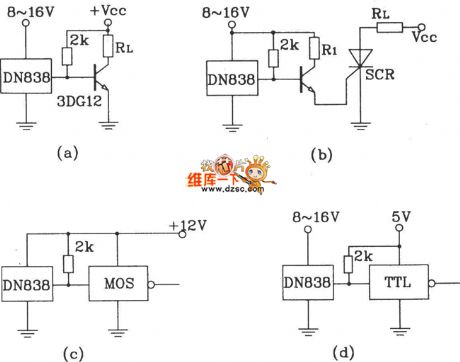
The outputs of figure (a), (b), (c), (d) can directly drive the transistor, the SCR, the relay, the CMOS circuit and the TTL circuit.
(View)
View full Circuit Diagram | Comments | Reading(437)
The mains voltage dual-way crossing lime alarm circuit
Published:2011/7/4 21:41:00 Author:Borg | Keyword: mains voltage, dual-way, alarm circuit

See as Figure 1, one line of the mains voltage is stepped down by C3, stabilized by DW, rectified by VD6, VD7 and C2, and then a 12V stable DC voltage is delivered to the circuit. The other line is rectified by VD1, stepped down by R1, filtered by C1 and then a 10.5v voltage that is detecting the mains input signal change on RP1 and RP2. The gates of IC1A and IC1B compose the over-voltage circuit, IC1C is the low-voltage detector, IC1D is the switch, IC1F, IC1E and the voltage pottery YD and so on compose the audio pulse oscillator. The triode VT, relay J and so on compose the protection circuit. (View)
View full Circuit Diagram | Comments | Reading(522)
The practical phone burglarproof alarm circuit
Published:2011/7/5 8:09:00 Author:Borg | Keyword: burglarproof alarm

The circuit principleThe practical phone burglarproof alarm circuit is shown as above.
When the external wire of the phone is normal, there is a 48~60v DC voltage in the line, which triggers the dual-way triggering diode DV3 conducting by VD1, so the triode VT2 is saturated and conducting. Both VT3 and VT4 are blocked without the bias voltage on the basic pole, the LED is not glowing and alarming. When the external wire is used by others, the voltage is dropping to 10V or so, the dual-way triggering transistor VD3 is broken down. (View)
View full Circuit Diagram | Comments | Reading(522)
The auto alarm of money box or secret room being pried
Published:2011/7/4 21:47:00 Author:Borg | Keyword: auto alarm, money box
See as the figure, the circuit includes the box-door linked switch SB, electric switch, light control sound circuit and audio amplifier circuit, etc. Put the circuit in the closed secret chamber or money box, when it is pried, the circuit will make alarm sound of Ooo```Ooo``` (View)
View full Circuit Diagram | Comments | Reading(1920)
The vehicle or room timer alarm circuit
Published:2011/7/4 22:09:00 Author:Borg | Keyword: timer alarm
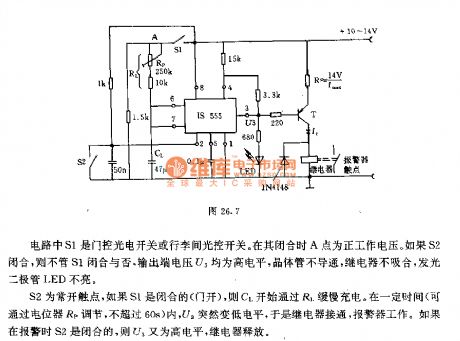
In the circuit, S1 is the door control photoelectric switch or the trunk light control switch. When it is pulling, the point A is the forward working voltage. If S2 is closed, whether S1 is closed or not, the voltage U3 on the output terminal will be a high LEV, the transistor is blocked, the relay is no pulling in, the LED is not glowing. S2 is the normally open contacator, if S1 is closed(the door is open), C1 will be charged by R1. In certain time(which can be adjusted by the potentiometer Rp), U3 is suddenly changed into the low LEV, so the relay is on and the alarm is working. (View)
View full Circuit Diagram | Comments | Reading(555)
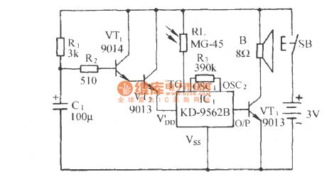
The gas putting out alarm circuit of auto start
Published:2011/7/4 22:38:00 Author:Borg | Keyword: putting out alarm, auto start

The principle circuit is shown in figure 1. The switch S is linked with the gas switch. When the gas valve is open, S is closed, if the gas is not lit, the LDR R2 is in a high LEV, the triode VT1 is conducting, which triggers the music integrated circuit to play music. At the same time, the transformer T1 is stepping up and outputting a pulse voltage with the peak value of 120Vpp, C1 is charged by R5 and C2 is charged by VD1. When C1 gets a certain voltage, the trigger VD2 is conducting, so is SCR, which makes the charged C2 discharges through T2 primary stage and SCR. (View)
View full Circuit Diagram | Comments | Reading(505)
Benz ABS system component position circuit
Published:2011/7/5 19:01:00 Author:Christina | Keyword: Benz, ABS, system, component position
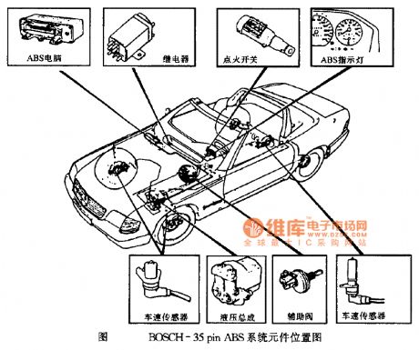
Benz ABS system component position circuit
Figure BOSCH-35pin ABS system component position circuit (View)
View full Circuit Diagram | Comments | Reading(911)
BENZ-560SEL automatic locking differential circuit
Published:2011/7/5 19:02:00 Author:Christina | Keyword: automatic locking, differential circuit
View full Circuit Diagram | Comments | Reading(499)
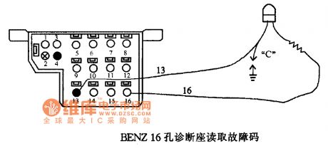
BENZ-124 automatic meshing four-wheel drive and automatic locking differential mechanism fault code circuit
Published:2011/7/5 19:04:00 Author:Christina | Keyword: automatic meshing, four-wheel drive, automatic locking, differential mechanism, fault code
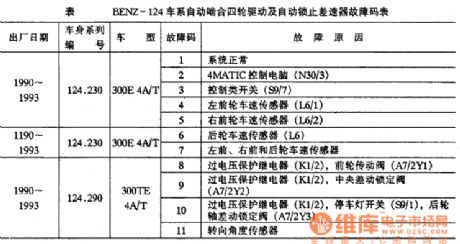
Table BENZ-124 automatic meshing four-wheel drive and automatic locking differential mechanism fault code circuit
(View)
View full Circuit Diagram | Comments | Reading(438)
The lighting early warning device circuit
Published:2011/7/4 21:18:00 Author:Borg | Keyword: lighting, early warning device

Working principle
The working principle is shown in figure 1, the feature of the circuit is that it can be adjusted to the self-oscillating state. The bias resistor in the figure can acquire the best relaxation feature. The oscillator is DC coupled, and the feedback branch is the collecting electrode of TR1 and the basic pole of TR2. The total gain of the circuit is set by the multi-turn (11,18 and 20) preset potentiometer VR1.The capacitor C3 sets the solid LEV of the TR2 emitting pole, and the capacitor C2 on VR1 smooth contactor is increasing the phase movement when it is oscillating.
(View)
View full Circuit Diagram | Comments | Reading(556)
Benz LED light connection circuit
Published:2011/7/5 19:05:00 Author:Christina | Keyword: Benz, LED light, connection circuit
View full Circuit Diagram | Comments | Reading(1245)
The watchdog circuit
Published:2011/7/5 8:21:00 Author:Borg | Keyword: watchdog circuit
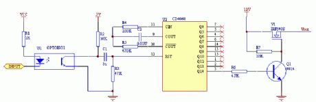
See as the figure: when the circuit is working, just a CD4060 reset pulse is delivered timely, Q1 will be sure to be blocked, so the NMOS tube under control is conducting and provides power for the circuit.
The virtue of the circuit is that the time is long, up to several minutes, which allows some systems to take a long time to reset. When the watchdog is fed with the pulse, a reset pulse is delivered to the auto counter by R2, C1 and R3, which makes sure Vout has output. (View)
View full Circuit Diagram | Comments | Reading(1921)
| Pages:1617/2234 At 2016011602160316041605160616071608160916101611161216131614161516161617161816191620Under 20 |
Circuit Categories
power supply circuit
Amplifier Circuit
Basic Circuit
LED and Light Circuit
Sensor Circuit
Signal Processing
Electrical Equipment Circuit
Control Circuit
Remote Control Circuit
A/D-D/A Converter Circuit
Audio Circuit
Measuring and Test Circuit
Communication Circuit
Computer-Related Circuit
555 Circuit
Automotive Circuit
Repairing Circuit