Control Circuit
The mains voltage dual-way crossing lime alarm circuit
Published:2011/7/4 21:41:00 Author:Borg | Keyword: mains voltage, dual-way, alarm circuit | From:SeekIC
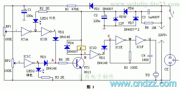
See as Figure 1, one line of the mains voltage is stepped down by C3, stabilized by DW, rectified by VD6, VD7 and C2, and then a 12V stable DC voltage is delivered to the circuit. The other line is rectified by VD1, stepped down by R1, filtered by C1 and then a 10.5v voltage that is detecting the mains input signal change on RP1 and RP2. The gates of IC1A and IC1B compose the over-voltage circuit, IC1C is the low-voltage detector, IC1D is the switch, IC1F, IC1E and the voltage pottery YD and so on compose the audio pulse oscillator. The triode VT, relay J and so on compose the protection circuit.
Reprinted Url Of This Article:
http://www.seekic.com/circuit_diagram/Control_Circuit/The_mains_voltage_dual_way_crossing_lime_alarm_circuit.html
Print this Page | Comments | Reading(3)

Article Categories
power supply circuit
Amplifier Circuit
Basic Circuit
LED and Light Circuit
Sensor Circuit
Signal Processing
Electrical Equipment Circuit
Control Circuit
Remote Control Circuit
A/D-D/A Converter Circuit
Audio Circuit
Measuring and Test Circuit
Communication Circuit
Computer-Related Circuit
555 Circuit
Automotive Circuit
Repairing Circuit
Code: