Control Circuit
The vehicle or room timer alarm circuit
Published:2011/7/4 22:09:00 Author:Borg | Keyword: timer alarm | From:SeekIC

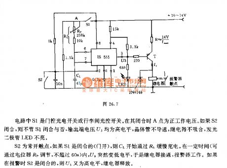
In the circuit, S1 is the door control photoelectric switch or the trunk light control switch. When it is pulling, the point A is the forward working voltage. If S2 is closed, whether S1 is closed or not, the voltage U3 on the output terminal will be a high LEV, the transistor is blocked, the relay is no pulling in, the LED is not glowing. S2 is the normally open contacator, if S1 is closed(the door is open), C1 will be charged by R1. In certain time(which can be adjusted by the potentiometer Rp), U3 is suddenly changed into the low LEV, so the relay is on and the alarm is working.
Reprinted Url Of This Article:
http://www.seekic.com/circuit_diagram/Control_Circuit/The_vehicle_or_room_timer_alarm_circuit.html
Print this Page | Comments | Reading(3)

Article Categories
power supply circuit
Amplifier Circuit
Basic Circuit
LED and Light Circuit
Sensor Circuit
Signal Processing
Electrical Equipment Circuit
Control Circuit
Remote Control Circuit
A/D-D/A Converter Circuit
Audio Circuit
Measuring and Test Circuit
Communication Circuit
Computer-Related Circuit
555 Circuit
Automotive Circuit
Repairing Circuit
Code: