
Circuit Diagram
Index 1610
The typical application circuit of digital output angle sensor signal regulator UZZ9001
Published:2011/6/28 7:50:00 Author:qqtang | Keyword: typical application circuit, output angle

In the figure is the typical application circuit of UZZ9001. C represents the decoupling capacitor, SPI input/output connector can directly couple with single chip machine(μC), UZZ9001 can be set by the single chip machine. The error of the measuring angle of UZZ9001 is about ±0.35o.
(View)
View full Circuit Diagram | Comments | Reading(471)
Mazda 96TAURUS alarm system circuit
Published:2011/7/4 0:42:00 Author:John | Keyword: alarm system

Mazda 96TAURUS alarm system circuit is shown.
(View)
View full Circuit Diagram | Comments | Reading(633)
Mazda 96TAURUS ABS circuit
Published:2011/7/4 0:41:00 Author:John | Keyword: ABS
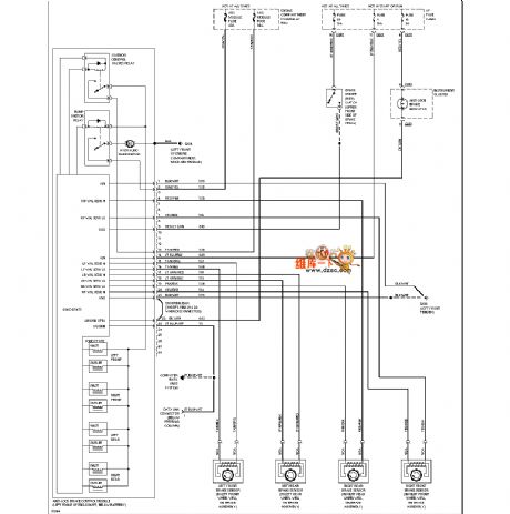
Mazda 96TAURUS ABS circuit is shown.
(View)
View full Circuit Diagram | Comments | Reading(623)
Mazda 96TAURUS power supply circuit
Published:2011/7/4 0:41:00 Author:John | Keyword: power supply

View full Circuit Diagram | Comments | Reading(573)
JFET broadband push-pull amplifier circuit
Published:2011/7/4 0:41:00 Author:John | Keyword: push-pull amplifier

The practical RF circuit is just as shown. This is prototyp developed from a similar circuit based on Doug DeMaw’s masterpiece named WIFB's QRPNotebook (ARRL, 99r, Main Street, Newington, CT06111). The affecting amplification component is JFET and the ideal operating frequency ranges from DC to VHF band. The ever very popular MPF 102 or its equivalent replacement components such as SK, ECG, NTE series devices can be used as available devices. ZN4416 can also be used. We are using the NTE-451-type JFET transistors, whose transconductance is up to 4000mS (micro- west E-Siemens). Besides, leakage current is from 4mA to 10mA, power consumption is 310mW and the maximum noise value is 4dB.
(View)
View full Circuit Diagram | Comments | Reading(1940)
IF amplifier with a crystal filter circuit
Published:2011/7/4 0:40:00 Author:John | Keyword: IF amplifier, crystal filter

The IF amplifier shown in the figure is based on the design of popular MC-1350P IC. The chip can be gotten by mail from the accessory store or from the smaller stores. This chip is basically the deformation of LM-1490 type and LM-1590 type circuits, but it is easier to use.
If MC-135OP components are not easy to find, the exactly same chip can be found in the online service instead, such as ECG or NTE. These series of components can be bought in the local electronic parts dealers, which are for service and repair shops use. The performance of using MC-1350P chip is identical to that of NTE-746 chip (as well as ECG-746).
(View)
View full Circuit Diagram | Comments | Reading(3272)
The wireless emitter microphone circuit--high sensitivity microphone circuit production
Published:2011/6/24 8:01:00 Author:qqtang | Keyword: wireless, emitter microphone, high sensitivity
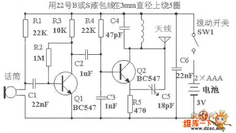
The circuit is simple and cheap, whose output power is not higher than 5-8mV, the emitting range is about 300m in citizen area, the signal is received with a FM radio, which indicates its good sensitivity and clearance, the most challenging part of designing the circuit is making a 3V power supply and a half-wave aerial have this emitting capability. Besides, as the circuit needs few elements, so the circuit can be put in a match box (which is a little bigger than the local match box) as the wiretap.
(View)
View full Circuit Diagram | Comments | Reading(1745)
The typical application circuit of low-power programmable sensor signal processor TSS400-S1/S2
Published:2011/6/28 7:51:00 Author:qqtang | Keyword: application circuit, low-power, signal processor

The typical application circuit of TSS400-S1/S2 is shown in the figure. This system is powered by the 3V LI battery(E), C1 and C2 is the decoupling capacitor of the power supply. The crystal frequency is 32.768KHz. The external storage is made of two pieces of 512 byte E2PROM of 24C04 type. In the dotted line frame is the silicon pressure sensor. With the temperature compensatory software, we can get the test precision and the 12-bit ADC pressure value. In the figure, all the analog wires are linked to USDD terminal, the sensor is powered only when it needs D/A conversion, by which the energy can be saved.
(View)
View full Circuit Diagram | Comments | Reading(547)
The general construction arrangement circuit of the low-power programmable sensor signal processor TSS400-S2
Published:2011/6/28 7:52:00 Author:qqtang | Keyword: general construction, low-power, programmable sensor

The general connection system allows a single way communication in a second line bus. This general line can be the twisted pair. Under the requirement of the host, the data are sent to the host from the affiliated machine. When the general line is effective, the affiliated host can also be started to send data asynchronously. The general connection of TSS400-S2 is shown in the figure. In the circuit, there is a chip general connector circuit TSS721. By the order of ENBUS, the distant reading of the additional module can be completed.
(View)
View full Circuit Diagram | Comments | Reading(595)
The typical system layout circuit of the low-power programmable sensor signal processor TSS400-S1
Published:2011/6/28 7:52:00 Author:qqtang | Keyword: typical system layout, low-power, signal processor

View full Circuit Diagram | Comments | Reading(501)
The TD-5 ultra-sonic micro fog humidifier circuit
Published:2011/6/24 8:02:00 Author:qqtang | Keyword: ultra-sonic, fog humidifier

T-power supply transformer FU-fuse VT-triode L1,L2,L3-the inductor B-voltage pottery power switch S-N-magnet ring buoy SL-water level switch
RP1-fog volume control switch RP2-adjustable resistor
(View)
View full Circuit Diagram | Comments | Reading(1175)
The gate drive circuit with the maximum 90% duty cycle
Published:2011/7/4 22:46:00 Author:Lucas | Keyword: gate drive , maximum , 90%, duty cycle

The key of the circuit is that the capacitive coupling circuit and VD1 form the clamp circuit. The output signal of secondary side in pulse transformer Tl is positive, that means up is positive while under is negative, the output signal can make VD2 and VD3 turn off by C2 to provide drive signal for the power MOSFET gate and make it turn on; Tl secondary side output signal is negative, that means up is negative while under is positive, due to the clamping effect of VD1, VD2 and VD3 are turned off, VTl is saturated conduction, the power MOS-FET gate charges and discharges rapidly to reduce the power MOSFET on / off delay time.
(View)
View full Circuit Diagram | Comments | Reading(833)
The interface circuit between MOSFET and logic level composed of NE555
Published:2011/7/4 22:32:00 Author:Lucas | Keyword: interface circuit , MOSFET , logic level

In the circuit, NE555 is the astable multivibrator with the oscillation frequency in 70KHz, and it uses the control input signal of reset pin (pin 4) to control its oscillation on / off state. When pin 4 input is in high level, the oscillator generates oscillation, and low level will stop the oscillation. The pin 3 of NE555 output can provide input voltage for the doubler rectifier circuit composed of VD1, VD2, C3 and C4 form provides the input voltage doubler rectifier circuit, then the output of the doubler rectifier circuit is about 8.5 V. Control signal can control VT2 on-off state, and the load of VT2 can be a relay.
(View)
View full Circuit Diagram | Comments | Reading(2552)
Motor speed control circuit composed of NE556
Published:2011/7/2 21:49:00 Author:Lucas | Keyword: Motor speed, control

NE556 chip has two timers with exactly the same functions: one timer is the astable multivibrator circuit, of which output is used as the trigger signal; the other is the monostable multivibrator circuit, of which time constant is adjusted by RP1. It constitutes the motor control circuit with constant frequency and adjustable duty cycle. Oscillation frequency f = 1.44 / [(R2 +2 R3) Cl], the duty cycle D = [1.6 (Rl ten R (RP1) Cl] [(R2+ 2R3) C1]. The small duty cycle will start the moyor. VTl uses 2SD42O transistor with Ic = lOA, h (EF) in 1000 or more to directly drive motor.
(View)
View full Circuit Diagram | Comments | Reading(5381)
Positioning control circuit composed of μA709
Published:2011/7/1 21:26:00 Author:Lucas | Keyword: Positioning control
In the circuit, Al gain is about 10 times, and the total circuit gain is about 30 times. Supply voltage is ± 35V. Al's power supply voltage is 13V, which is stabilized by VDz1 and VDz2 voltage-regulator tube from ± 35V. RP1 is used to adjust the offset voltage of A1. When the input voltage is zero, adjusting RPl can make the position is section start. If the input is connected to D / A converter, you can use digitto locate position.
(View)
View full Circuit Diagram | Comments | Reading(633)
Motor control circuit composed of NE555
Published:2011/7/1 21:29:00 Author:Lucas | Keyword: Motor control

Oscillation frequencyis decidedby the capacitor Cl, resistor Rl and so on, according to the chart component parameters, the oscillation frequency is 20 to 50KHz,and the withstand voltage of VT1 is 5OV. Using BUZll cancontrol the motor current in 2OA.
(View)
View full Circuit Diagram | Comments | Reading(10866)
Motor positive, reversal rotation control circuit composed of MOSFET
Published:2011/7/1 22:42:00 Author:Lucas | Keyword: Motor, positive, reversal, rotation control , MOSFET

Plus signal ˉ Q can drive the left and right bridge to control the motor positive, reversal rotation. When Q input is in high level, VT5 is conducted, and VT3 is quickly stopped by VD2. Rl can limit the diode current in PCl, so VTl is conducted after delaying several μs. If ˉ Q input is in low level, then VT6 is stopped, and the current flowing VD4 rapid decreases, then the optical coupler PC2 is stopped. R6 resistor make VT2 deadline, then the power charges to the gate of the VT4 and make it turn on by VD4, R4 and R5.
(View)
View full Circuit Diagram | Comments | Reading(1198)
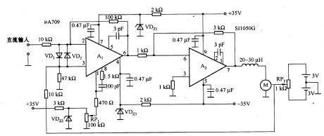
The DC motor servo circuit with compensation performance composed of μA709
Published:2011/7/2 20:50:00 Author:Lucas | Keyword: DC motor , servo circuit , compensation performance

The circuit is used for small self-balancing recorder. The input stage uses the μA709 high-gain op amp, and output power amplifier stage uses differential amplifier. The circuit is added the feedback to reach the desired frequency characteristics.Integral feature is achieved by connecting Cl, C2 in series in the feedback circuit and differential compensation, and the time constant is determined by C3 and Rl. If Cl, C2 are shorted, the error of the system converted to the input is about lOmV. Afetr connecting Cl, C2 and accessing integral compensation, and the loop gain is about more than 7,000 times, so the static error is zero.
(View)
View full Circuit Diagram | Comments | Reading(2698)
DC motor servo circuit composed of μA741
Published:2011/7/4 19:10:00 Author:Lucas | Keyword: DC motor, servo circuit

In the circuit, R1 and R2 is to limit all power supply voltage to add on the bridge, and thus change the size of the input signal. RP1 is used for the location set, but the servo motor position is mainly depends on the another voltage signal. At this time, if Al's inverting input end is applied voltage signal, the servo finally steady state is to make the potential of RP2 and the input signal of inverting input end be the same. The bases of VTl and VT2 power transistors are connected with diodes VD3 and VD4 to skillfully applied bias.
(View)
View full Circuit Diagram | Comments | Reading(4695)
33MHz multi-output clock driver circuit
Published:2011/7/5 6:06:00 Author:Lucas | Keyword: 33MHz , multi-output , clock, driver circuit

It is the clock driver circuit composed of P149FC32805, and the maximum clock frequency is 133MHz. It is suitable for the distribution of clock signal in the substrate. Each output delays in less than 270ps and is easy to do synchronization management.
(View)
View full Circuit Diagram | Comments | Reading(597)
| Pages:1610/2234 At 2016011602160316041605160616071608160916101611161216131614161516161617161816191620Under 20 |
Circuit Categories
power supply circuit
Amplifier Circuit
Basic Circuit
LED and Light Circuit
Sensor Circuit
Signal Processing
Electrical Equipment Circuit
Control Circuit
Remote Control Circuit
A/D-D/A Converter Circuit
Audio Circuit
Measuring and Test Circuit
Communication Circuit
Computer-Related Circuit
555 Circuit
Automotive Circuit
Repairing Circuit