
Circuit Diagram
Index 1609
The Toyota A340E“R” back gear oil circuit
Published:2011/6/24 7:41:00 Author:Seven | Keyword: Toyota, back gear

The Toyota A340E“R” back gear oil circuit is shown in the figure.
(View)
View full Circuit Diagram | Comments | Reading(1488)
The serial connection current expanding circuit of 3-terminal regulated chip
Published:2011/6/24 7:41:00 Author:Seven | Keyword: serial connection, 3-terminal regulated chip
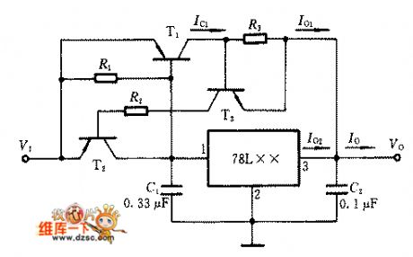
When a current that is higher than 0.1A is needed, we can use other types of integrated circuit the following current expanding circuit. The output current of the 78 series circuit is I0=I01+I02, of which I01=Ic1, I02≈0.7V/R1. This serial connection current expanding circuit of 3-terminal regulated chip has the function of over-current protection, when it is normally working, T2 and T3 are blocked; when IO is over-current, IO1 is increasing, the voltage drop of the current limiting resistor R3 makes T3 and T2 conducting, the VBE of T1 is falling ,which limits the IC1 of T1 and it also protects T1 from being broken of over current.
(View)
View full Circuit Diagram | Comments | Reading(599)
The FM modulation wireless microphone circuit
Published:2011/6/24 7:41:00 Author:Seven | Keyword: FM modulation, wireless microphone

In the figure is the FM modulation wireless microphone circuit, in fact, this is the FM modulation commutator whose frequency is 80~90MHz. The working principle is as follows: the microphone converts the sound signal into the voltage signal which is added on the VT1 basic pole by the coupling capacitor C1, the current in the emitting pole is switched into the voltage, and the voltage change on R1 makes the collecting electrode voltage change, then the capacitor of the collecting pole changes and the oscillating frequency changes, which modulates FM. The modulating signal is emitted after it's been magnified by VT2.
(View)
View full Circuit Diagram | Comments | Reading(1204)
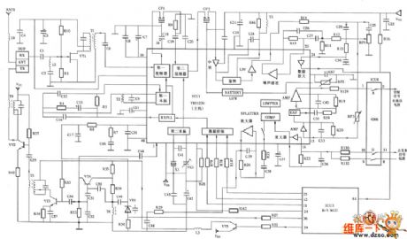
TA7770 dolby noise reduction integrated circuit
Published:2011/7/5 0:58:00 Author:chopper | Keyword: dolby, noise reduction, integrated circuit
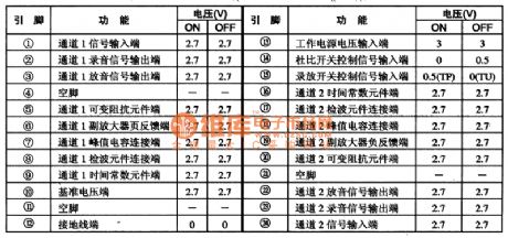
TA7770 is a dolby noise reduction integrated circuit produced by Japanese company TOSHIBA,it is applied to slap-up low-voltage walkman,repeater and other acoustic equipments.1.function characteristicsTA7770 integrated circuit includes two double channel dolby noise reduction circuits of same function,benchmark voltage circuit,dolby switch control circuit and other miscellaneous function circuits.2.function and data of pinsTA7770 integrated circuit adopts dual inline 2 pinned package. The function and data of pins of the integrated circuit are shown as the chart 1.
(View)
View full Circuit Diagram | Comments | Reading(514)
The controllable silicon(thyristor) element equivalent circuit
Published:2011/6/24 7:40:00 Author:Seven | Keyword: controllable silicon, equivalent circuit

The controllable silicon(thyristor) is a 4-layer, 3-terminal element, which has 3 PN knot, when analysing its principle, we can regard it as an element composed of a PNP and a NPN, its equivalent chart is in figure 1.
When the positive pole A is added with a forward voltage, BG1 and BG2 are both in amplifying state. At the moment, if we input a positive trigger signal from the control pole G, then BG2 will have a basic current ib2 in it, after the current is amplified by BG2, the collecting electrode current is ic2=β2ib2. As the collecting electrodes of BG2 and BG1 are connected directly, so ib1=ic2. (View)
View full Circuit Diagram | Comments | Reading(524)
The golf AUM motor circuit
Published:2011/7/4 4:25:00 Author:Seven | Keyword: golf, AUM motor

The golf AUM motor circuit is shown as above.
D-lighting switch; J271-multiple injection power supply relay, which is in the protecion shell on the left side of the engine room(the control No. is 428);S10-fuse on the holder 10; S229-fuse on the holder 29; S231-fuse on the holder 31; T2-plug, 2 holes, on the left side of the engine room; T6-plug,6 holes,brown, in the plug protection shell, on the left side of the flow tank; T14a-plug, 14 holes, on the left side of the wire way in the engine room (View)
View full Circuit Diagram | Comments | Reading(1090)
The electric fish trap circuit (2)
Published:2011/6/23 0:46:00 Author:qqtang | Keyword: fish trap

Only by changing several data can the circuit use 12V batteries. Considering the current istwo high, the power supply is designed to be 24V. The circuit should make full use of the component parameter, so that the circuit will be small-sized and efficient.
(View)
View full Circuit Diagram | Comments | Reading(2556)
TA8105N monolithic stereo playback integrated circuit
Published:2011/7/5 1:12:00 Author:chopper | Keyword: monolithic, stereo, playback, integrated circuit


TA8105N is a monolithic playback integrated circuit produced by Company TOSHIBA,and it is applied to mini acoustic system like low-voltage walkman and so on.1.inner circuit and function of pins The inner circuit of TTA8105/N integrated package includes two same preposing equilibrium amplifier circuits,power amplifier circuit and tape track switching circuit. TTA8105/N integrated circuit is of two package structure,TA8105/N adopts dual inline 2 pinned package,TA8105F adopts dual inline 24 pinned flat package.
(View)
View full Circuit Diagram | Comments | Reading(1298)
The electric mosquito swatter circuit
Published:2011/6/24 8:02:00 Author:qqtang | Keyword: electric, mosquito swatter

Instructions: (1) this circuit is the picture of the typical electric mosquito swatter; (2) oscillating transformer: the coil is sealed by insulated paint, so the turns are unknown, which is to be provided, the output voltage of the oscillating transformer is a AC, the peak value is 350v.(3) the oscillating transistor: as the amplifier parameters of the pipes are different, when we feel hot of the transistor while using the swatter, we can install a resistor of 100Ω or so to limit the basic electrode current, then it is cooled.(4) rectifier part
(View)
View full Circuit Diagram | Comments | Reading(10660)
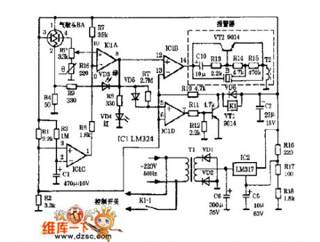
The gas fog alarm circuit
Published:2011/6/24 8:04:00 Author:qqtang | Keyword: gas, fog alarm

See as the figure, when there is combustible gas. The conductance of TGS308 gas sensor is increasing, the voltage is picked out by the potentiometer RP1 floating spot, and its value rises to 20v from the normal 3V effectively. The risen voltage is added to the transistor VT1 by the diode and the 4.7kΩ resistor, which makes VTI conducting, and the dual-direction transistor 2N6070A is conducting with VT1. Therefore, the full-wave AC conductance H generates a sound of 90dB, which fulfills alarming. H is a 20V AC alarm of De1taJ6003168. When the gas disappears from the sensor, the circuit gets to it primary state.
(View)
View full Circuit Diagram | Comments | Reading(500)
The light control switch circuit of LDR
Published:2011/6/28 7:53:00 Author:qqtang | Keyword: light control switch, LDR

The power switch can be made of power MOS FET and the sensitive element can be the LDR. The light is shed on the LDR, it is in low resistance and there is a signal on the grid of the sound effect transistor, the source-drain is conducting, so the state of the relay is changed by K, which generates sounds and fulfills the control function. If the LDR is fixed at the low LEV sector, there won't be light on the LDR when it's dark outside, so the resistance of the LDR is high and the grid of the VMOS pipe is high, which makes the lamp L light.
(View)
View full Circuit Diagram | Comments | Reading(1087)
The button recharging Li icon battery charge circuit
Published:2011/7/4 4:08:00 Author:qqtang | Keyword: button, Li icon, battery charge

View full Circuit Diagram | Comments | Reading(550)
The Chang An Auto fuse and relay circuit
Published:2011/7/4 4:09:00 Author:qqtang | Keyword: Chang An, Auto, fuse, relay
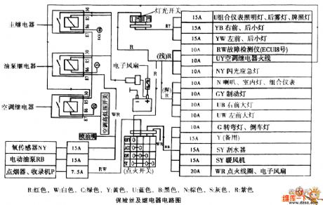
The Chang An Auto fuse and relay circuit is shown as above.
R:red, W:white, C:green, Y:yellow, U:bule, B:black; N:brown, S:grey, R:purple
The fuse and relay circuit (View)
View full Circuit Diagram | Comments | Reading(515)
The internal circuit of the low voltage special integrated chip MC3X164
Published:2011/7/4 4:10:00 Author:qqtang | Keyword: internal circuit, low voltage, special integrated chip

View full Circuit Diagram | Comments | Reading(521)
The internal circuit of the HN911 heat releasing electric infrared probe module
Published:2011/6/12 21:38:00 Author:qqtang | Keyword: internal circuit, probe module
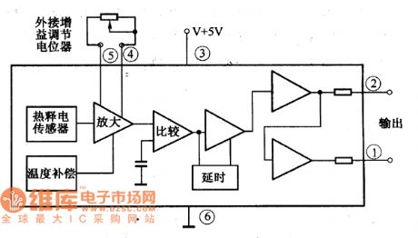
The HN911 heat releasing electric infrared probe model is a sensing device which consists of the heat releasing electric infrared sensor, amplifier signal process circuit, time delay circuit and high/low LEV output circuit. It characterizes high sensitivity, high anti-noise ability, low temperature resistance and convenient use, etc, which is used to detect the infrared ray energy which is emitted by human bodies, it is suitable for the detection alarm system of human movement.The internal circuit of the HN911 heat releasing electric infrared probe module is shown in the figure.
Figure:The internal circuit of the HN911 heat releasing electric infrared probe module (View)
View full Circuit Diagram | Comments | Reading(479)
The module outline circuit of the HN911 heat releasing electric
Published:2011/6/12 21:38:00 Author:qqtang | Keyword: module outline, infrared probe
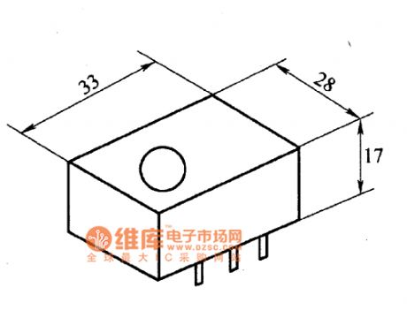
The HN911 heat releasing electric infrared probe model is a sensing device which consists of the heat releasing electric infrared sensor, amplifier signal process circuit, time delay circuit and high/low LEV output circuit. It characterizes high sensitivity, high anti-noise ability, low temperature resistance and convenient use, etc, which is used to detect the infrared ray energy which is emitted by human bodies, it is suitable for the detection alarm system of human movement.The module outline of HN911 heat releasing electric infrared probe is shown in the figure.
Figure:The module outline of HN911 heat releasing electric infrared probe (View)
View full Circuit Diagram | Comments | Reading(395)
The auto cooker hood circuit (01)
Published:2011/6/19 19:52:00 Author:qqtang | Keyword: cooker hood
View full Circuit Diagram | Comments | Reading(878)
The host RF circuit of Telsda HW838 (4) P/ISD—LED wireless telephone
Published:2011/6/23 0:33:00 Author:qqtang | Keyword: RF circuit, wireless telephone
View full Circuit Diagram | Comments | Reading(879)
The Changhong hp(5168) projection green primary video amplifier circuit
Published:2011/6/23 0:33:00 Author:qqtang | Keyword: projection, green primary, video amplifier circuit

The Changhong hp(5168) projection green primary video amplifier circuit is shown in the figure.
(View)
View full Circuit Diagram | Comments | Reading(551)
The MOSFET A amplifier circuit
Published:2011/6/23 0:44:00 Author:qqtang | Keyword: MOSFET A, amplifier circuit

The MOSFET A amplifier circuit is shown in theabove figure.
C1-1uF, 35V R4-20 ohms, 5WC2-470uF, 35v electrolytic R5-1K ohms, 1/4WC3-0.1uF, 35v Rg-220 ohms, 1/4W (see text)D1,D2-1N914 Diode Rp-10K-100K dual pot(audio taper)Q1-IRF 513MOSFET R1-4.7K ohms,1/4WR2-100k ohms,1/4W R3-220K ohms,1/4W(see text)All resistors are metal film. C1 is a film type such as polypropylene. Bypass C2 with a 1uF polypropylene cape. (View)
View full Circuit Diagram | Comments | Reading(816)
| Pages:1609/2234 At 2016011602160316041605160616071608160916101611161216131614161516161617161816191620Under 20 |
Circuit Categories
power supply circuit
Amplifier Circuit
Basic Circuit
LED and Light Circuit
Sensor Circuit
Signal Processing
Electrical Equipment Circuit
Control Circuit
Remote Control Circuit
A/D-D/A Converter Circuit
Audio Circuit
Measuring and Test Circuit
Communication Circuit
Computer-Related Circuit
555 Circuit
Automotive Circuit
Repairing Circuit