
Circuit Diagram
Index 1603
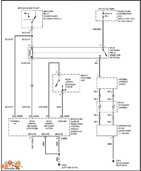
BMW defogger circuit
Published:2011/7/5 22:17:00 Author:Christina | Keyword: BMW, defogger
View full Circuit Diagram | Comments | Reading(457)
ChangFeng LieBao SUV 6G72 engine ignition system circuit
Published:2011/7/5 22:13:00 Author:Christina | Keyword: ChangFeng, LieBao, SUV, engine, ignition system

The ChangFeng LieBao SUV 6G72 engine ignition system circuit is as shown:
(View)
View full Circuit Diagram | Comments | Reading(890)
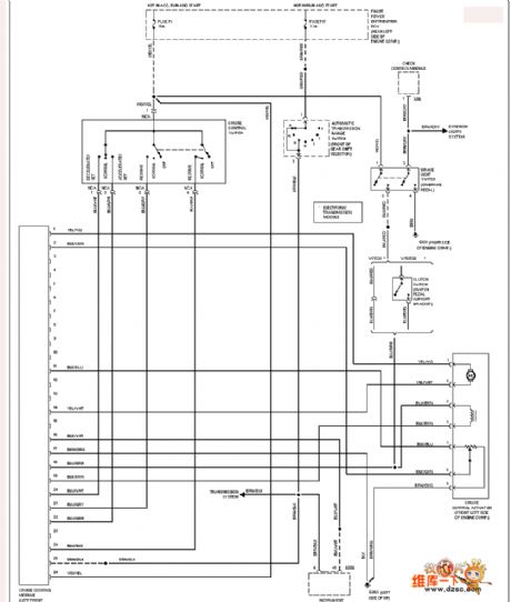
BMW cruise control circuit
Published:2011/7/5 22:14:00 Author:Christina | Keyword: BMW, cruise, control
View full Circuit Diagram | Comments | Reading(762)
Hall proximity switch CNC machine tool PLC circuit
Published:2011/7/5 22:02:00 Author:Christina | Keyword: Hall proximity switch, CNC machine tool, PLC circuit

This circuit can be used in the CNC machine tool programmable controller, the precision can be 0.02mm, also it can be used in the high speed punches, the material cutting and feeding of the complex molds, and the stroke control.
(View)
View full Circuit Diagram | Comments | Reading(949)
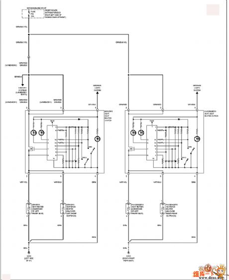
BMW seat heating circuit
Published:2011/7/6 1:47:00 Author:Christina | Keyword: BMW, seat heating
View full Circuit Diagram | Comments | Reading(523)
Two-wire type smart Hall sensor IC application circuit
Published:2011/7/6 1:38:00 Author:Christina | Keyword: Two-wire type, smart, Hall sensor, IC, application circuit

The typical application circuit of the TLE4941 is as shown in the figure. We can change the input current into the voltage signal Vo by using the resistance R, and this voltage signal is connected with the digital voltmeter (DVM) or sent to the single-chip microcomputer with the ADC.
(View)
View full Circuit Diagram | Comments | Reading(625)
BMW automatic memory rearview mirror circuit
Published:2011/7/6 1:48:00 Author:Christina | Keyword: BMW, automatic memory, rearview mirror
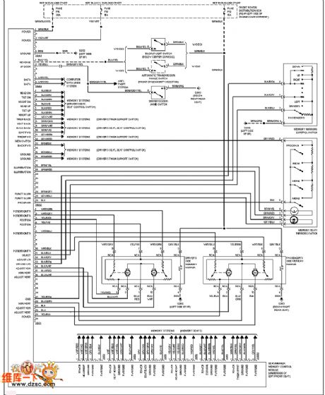
BMW automatic memory rearview mirror circuit
(View)
View full Circuit Diagram | Comments | Reading(492)
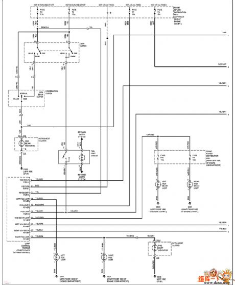
BMW (without the DRL1) headlamp circuit
Published:2011/7/6 1:28:00 Author:Christina | Keyword: BMW, DRL1, headlamp circuit
View full Circuit Diagram | Comments | Reading(439)
Buick century power distribution & grounding circuit
Published:2011/7/6 1:52:00 Author:Christina | Keyword: Buick century, power distribution, grounding
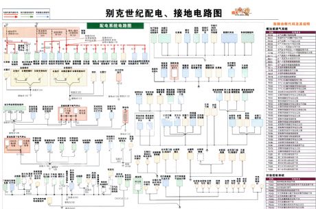
The Buick century power distribution & grounding circuit is as shown in the figure:
(View)
View full Circuit Diagram | Comments | Reading(399)
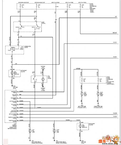
BMW (with the DRL1) headlamp circuit
Published:2011/7/6 1:27:00 Author:Christina | Keyword: BMW, DRL1, headlamp
View full Circuit Diagram | Comments | Reading(444)
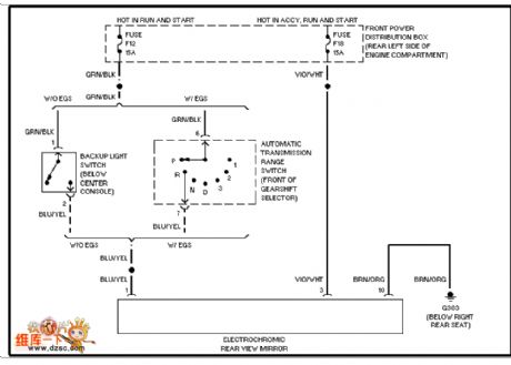
BMW photosensitive discoloration rearview mirror circuit
Published:2011/7/6 1:55:00 Author:Christina | Keyword: BMW, photosensitive, discoloration, rearview mirror
View full Circuit Diagram | Comments | Reading(526)
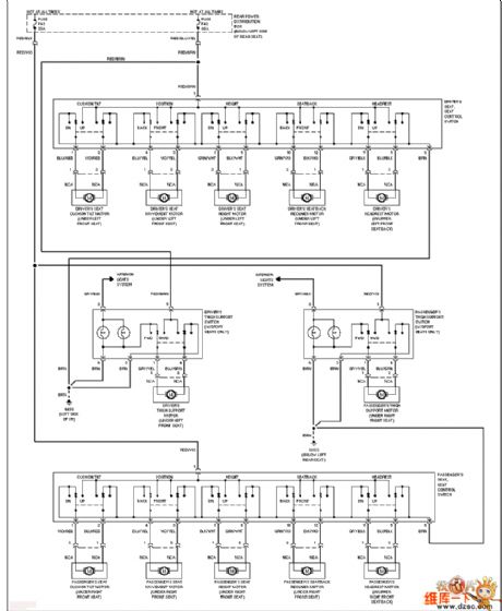
BMW electric seat circuit
Published:2011/7/6 1:57:00 Author:Christina | Keyword: BMW, electric seat
View full Circuit Diagram | Comments | Reading(463)
Intelligent humidity measuring instrument circuit composed of the HM1500/1520 humidity sensor and single-chip microcomputer
Published:2011/7/6 2:14:00 Author:Christina | Keyword: Intelligent, humidity measuring, instrument, humidity sensor, single-chip microcomputer
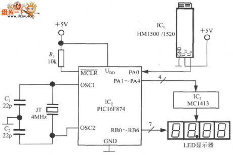
The intelligent humidity measuring instrument circuit which is composed of the HM1500/1520 humidity sensor and single-chip microcomputer is as shown in the figure. This instrument uses the +5V power supply, and has 4 common cathode LED digital tubes. This circuit uses three ICs: IC1 is the HM1500/1520 humidity sensor, IC2 is the 10-bit ADC single-chip microcomputer PIC16F874 which is produced by the United States Microchip company, IC3 is the 7 darlington invert driver array MC1413. The PIC16F874 is designed as one kind of cost-effective 8-bit SCM, it has the successive approximation type 10-bit A/D convertr, and it can convert 8 channels of humidity signal, now we only use one of the 8 channels.
(View)
View full Circuit Diagram | Comments | Reading(1363)
RF signal receiving strength indicator circuit composed of the MAX2015
Published:2011/7/6 2:34:00 Author:Christina | Keyword: RF signal, receiving, strength, indicator

The RF signal receiving strength indicator circuit which is composed of the MAX2015 is as shown in the figure. The RF signal is connected with the IN+ port through the coupling capacitance C1, the IN- port is connected with the ground through the coupling capacitance C2. The internal 50Ω resistances of the IN+ and IN- ports can be matched with the 50MHz~3.0GHz RF circuit. The capacities of C1 and C2 are 680 pF. The C3 and C4 are the power-supply decoupling capacitance. If you short connect the OUT port with the SET port, the MAX2015 will be in the detection mode. The output voltage Vo of the OUT port adds to the digital voltmeter to display the strength of the receiving RF signal.
(View)
View full Circuit Diagram | Comments | Reading(973)
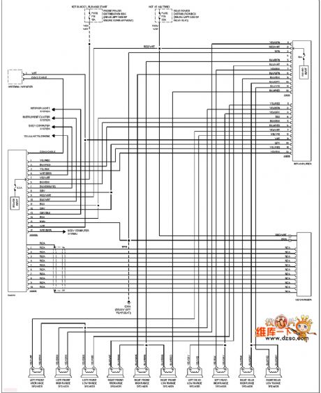
BMW sound circuit
Published:2011/7/6 2:14:00 Author:Christina | Keyword: BMW, sound circuit
View full Circuit Diagram | Comments | Reading(472)
Jetta QianWei air conditioning & fan control circuit
Published:2011/7/6 2:17:00 Author:Christina | Keyword: Jetta, QianWei, air conditioning, fan control circuit
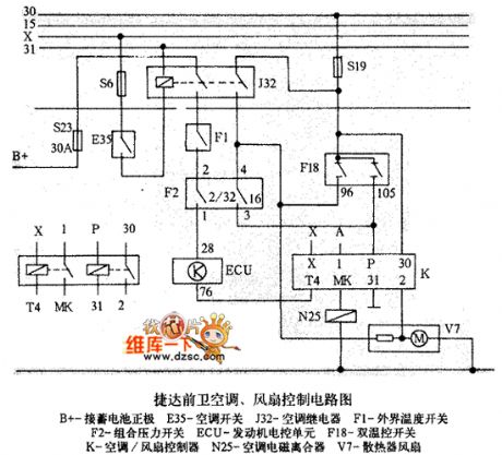
The Jetta QianWei air conditioning & fan control circuit is as shown in the figure:
(View)
View full Circuit Diagram | Comments | Reading(476)
RF power control circuit
Published:2011/7/6 2:42:00 Author:Christina | Keyword: RF, power control
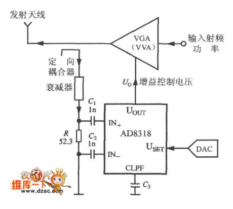
The working principle of the RF power control circuit is as shown in the figure. The controlled object can be the power amplifier (PA), the variable gain amplifier (VGA) and the variable voltage attenuator (VVA).etc. When you are selecting the control mode, you need to cut off the USET and UOUT pins. The measured RF power signal adds to the input port of the AD8318 through the directional coupler and the attenuator. The set voltage of AD8318 is got from the D/A converter (DAC). The gain control voltage which is output by the UOUT of AD8318 can be used to control the output power of VGA(or VVA).
(View)
View full Circuit Diagram | Comments | Reading(625)
Intelligent pressure measurement and control instrument circuit
Published:2011/7/6 2:18:00 Author:Christina | Keyword: Intelligent, pressure, measurement, control, instrument
Intelligent pressure measurement and control instrument circuit is as shown in the figure:
(View)
View full Circuit Diagram | Comments | Reading(605)
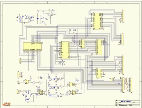
Simple telephone repair instrument circuit
Published:2011/7/6 2:43:00 Author:Christina | Keyword: Simple, telephone, repair instrument

The Simple telephone repair instrument circuit is as shown in the figure:
(View)
View full Circuit Diagram | Comments | Reading(1052)
Single-phase contact type variac voltage regulator circuit
Published:2011/7/6 2:26:00 Author:Christina | Keyword: Single-phase, contact type, variac, voltage regulator
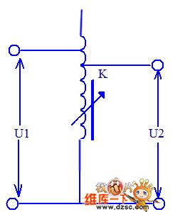
The Single-phase contact type variac voltage regulator circuit is as shown in the figure:
When the capacity of each variac is not enough, you can connect several variacs in parallel. In order to guarantee the equation of the secondary side voltages when it is operating and avoid to cause the potential difference, the adjustment of the parallel transformers must be synchronized. In addition, it needs an output port series reactor to evenly distribute the power. (View)
View full Circuit Diagram | Comments | Reading(838)
| Pages:1603/2234 At 2016011602160316041605160616071608160916101611161216131614161516161617161816191620Under 20 |
Circuit Categories
power supply circuit
Amplifier Circuit
Basic Circuit
LED and Light Circuit
Sensor Circuit
Signal Processing
Electrical Equipment Circuit
Control Circuit
Remote Control Circuit
A/D-D/A Converter Circuit
Audio Circuit
Measuring and Test Circuit
Communication Circuit
Computer-Related Circuit
555 Circuit
Automotive Circuit
Repairing Circuit