Control Circuit
RF power control circuit
Published:2011/7/6 2:42:00 Author:Christina | Keyword: RF, power control | From:SeekIC

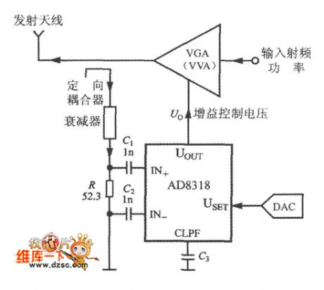
The working principle of the RF power control circuit is as shown in the figure. The controlled object can be the power amplifier (PA), the variable gain amplifier (VGA) and the variable voltage attenuator (VVA).etc. When you are selecting the control mode, you need to cut off the USET and UOUT pins. The measured RF power signal adds to the input port of the AD8318 through the directional coupler and the attenuator. The set voltage of AD8318 is got from the D/A converter (DAC). The gain control voltage which is output by the UOUT of AD8318 can be used to control the output power of VGA(or VVA).
Reprinted Url Of This Article:
http://www.seekic.com/circuit_diagram/Control_Circuit/RF_power_control_circuit.html
Print this Page | Comments | Reading(3)

Article Categories
power supply circuit
Amplifier Circuit
Basic Circuit
LED and Light Circuit
Sensor Circuit
Signal Processing
Electrical Equipment Circuit
Control Circuit
Remote Control Circuit
A/D-D/A Converter Circuit
Audio Circuit
Measuring and Test Circuit
Communication Circuit
Computer-Related Circuit
555 Circuit
Automotive Circuit
Repairing Circuit
Code: