
Circuit Diagram
Index 1618
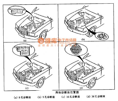
Benz TDCL position circuit
Published:2011/7/5 19:08:00 Author:Christina | Keyword: Benz, TDCL, position
View full Circuit Diagram | Comments | Reading(432)
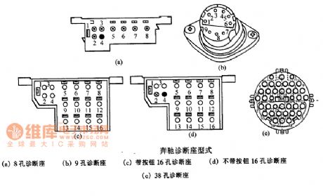
Benz TDCL type circuit
Published:2011/7/5 19:08:00 Author:Christina | Keyword: Benz, TDCL type
View full Circuit Diagram | Comments | Reading(458)
BMW8 series 850ci, 850csi anti-theft system circuit
Published:2011/7/5 19:09:00 Author:Christina | Keyword: BMW8 series, anti-theft system
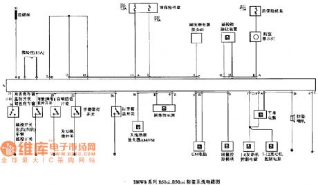
BMW8 series 850ci, 850csi anti-theft system circuit
(View)
View full Circuit Diagram | Comments | Reading(423)
The frequency converter circuit with a main speed setting box and linked set operational box
Published:2011/7/5 20:23:00 Author:Borg | Keyword: frequency converter, operational box

In the figure, FR-FG is the main speed setting part, FR-AL is the linked set operational box. In the circuit is the NFB which can connect with more than on FR-AL linked setting boxes and frequency converter, it can make several 3-phase motor run synchronously, and it is also use to synchronous acceleration/deceleration (speed regulation). The main speed regulation is done by the potentiometer RP. (View)
View full Circuit Diagram | Comments | Reading(886)
Multi-function adjustable general time relay circuit
Published:2011/7/5 20:27:00 Author:Christina | Keyword: Multi-function, adjustable, general time, relay circuit
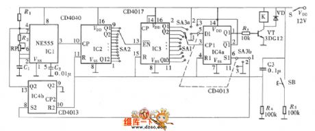
The multi-function of this circuit means that it has three kinds of operating modes: the delay closing , the delay releasing and the delay circulating . The delay closing means that after this relay is set, the relay will not close. Only when the preset time is up, the relay will close. The delay releasing is opposite withe the delay closing , the relay will close after the pre-boot, when the preset time is up, the relay will release. The delay closing and the delay releasing are disposable.
(View)
View full Circuit Diagram | Comments | Reading(828)
The alarm lamp circuit of reliable indicators
Published:2011/7/5 8:34:00 Author:Borg | Keyword: alarm lamp, reliable indicators

In many devices, there must be the reliable alarm lamps, and it does not allow the indicator to be cut off when the machine is malfunctioning, so the circuit with device indicator can be adopted.in the circuit, if La1 is lighting, La2 won't be light, and vice versa. The parameters of the circuit can easily be changed, so the circuit can be used in other situations. For example, to replace the 820Ω resistor by a transistor of large voltage and current with a 1.5kΩ, which can be used in the 50 or 100mA current load powered by the 24V voltage. (View)
View full Circuit Diagram | Comments | Reading(488)
ChangFeng LieBao SUV automatic transmission circuit
Published:2011/7/5 20:30:00 Author:Christina | Keyword: ChangFeng, LieBao, SUV, automatic transmission
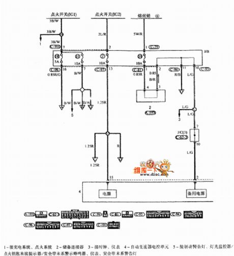
ChangFeng LieBao SUV automatic transmission circuit is as shown:
(View)
View full Circuit Diagram | Comments | Reading(437)
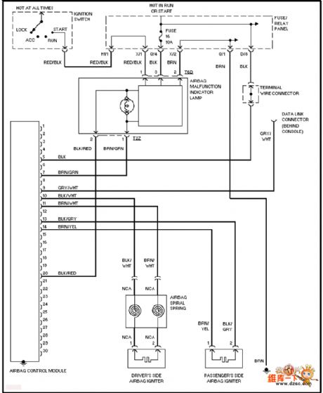
Volkswagen airbag circuit
Published:2011/7/5 20:02:00 Author:Christina | Keyword: Volkswagen, airbag circuit
View full Circuit Diagram | Comments | Reading(1761)
The door lock alarm with the time recognition function
Published:2011/7/5 8:46:00 Author:Borg | Keyword: door lock alarm, time recognition
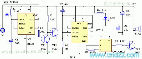
The circuit is shown in figure 1, which is composed of the 555 time-based integrated circuit and alarm integrated circuit. The time-based circuit IC1 consists of the temporary single steady trigger of T=4min or so with R1 and C1. Usually, IC1 is in the stable state, and the 3-pin of it outputs a low LEV, VT1 is blocked, VT2 is conducting, the capacitor C2 is shortened by VT2 and can't be charged, the 6-pin on the threshold of the time-based circuit IC2 is in a high LEV, while 3-pin is outputting a low LEV, the alarm sound integrated circuit IC3 is not working without power, the loudspeaker is silent. M is the touching electrode chip which is linked to the lock. (View)
View full Circuit Diagram | Comments | Reading(512)
Volkswagen alarm system circuit
Published:2011/7/5 20:06:00 Author:Christina | Keyword: Volkswagen, alarm system

View full Circuit Diagram | Comments | Reading(714)
ChangFeng LieBao SUV combination meter circuit
Published:2011/7/5 20:33:00 Author:Christina | Keyword: ChangFeng, LieBao, SUV, combination meter
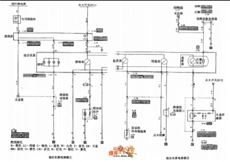
The ChangFeng LieBao SUV combination meter circuit is as shown in the figure:
(View)
View full Circuit Diagram | Comments | Reading(415)
BMW8 series anti-theft device location circuit
Published:2011/7/5 19:10:00 Author:Christina | Keyword: BMW8 series, anti-theft device, location circuit
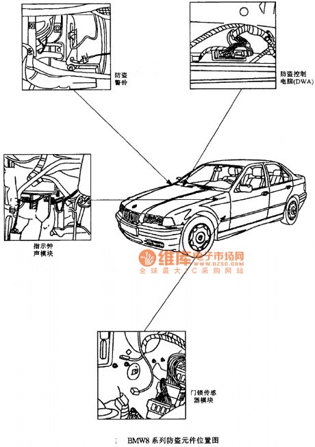
BMW8 series anti-theft device location circuit (View)
View full Circuit Diagram | Comments | Reading(417)
BMW7 series 740i E38DWA IV anti-theft system circuit (4)
Published:2011/7/5 19:12:00 Author:Christina | Keyword: BMW7 series, 740i, anti-theft system
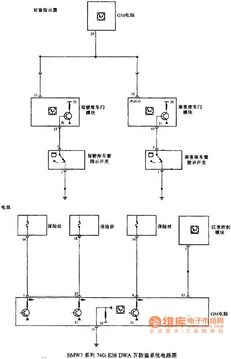
BMW7 series 740i E38DWA IV anti-theft system circuit (4)
(View)
View full Circuit Diagram | Comments | Reading(361)
BMW7 series 740i E38DWA IV anti-theft system circuit (3)
Published:2011/7/5 19:17:00 Author:Christina | Keyword: BMW7 series, 740i, anti-theft system
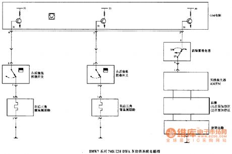
BMW7 series 740i E38DWA IV anti-theft system circuit (3)
(View)
View full Circuit Diagram | Comments | Reading(407)
The transistor and gate protection circuit
Published:2011/7/4 22:43:00 Author:Borg | Keyword: transistor, protection
View full Circuit Diagram | Comments | Reading(592)
DC-Servo parallel connection voltage stabilization power supply circuit
Published:2011/7/5 19:20:00 Author:Christina | Keyword: DC-Servo, parallel connection, voltage stabilization, power supply circuit

View full Circuit Diagram | Comments | Reading(1161)
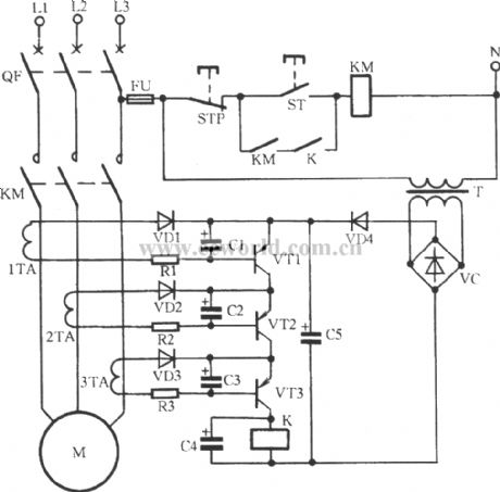
Full-automatic non-contact AC voltage stabilizer circuit
Published:2011/7/5 19:27:00 Author:Christina | Keyword: Full-automatic, non-contact, AC, voltage stabilizer


When the city electricity voltage is in the range of 150V~300V, this circuit can adjust the output voltage accurately and quickly.
The circuit is as shown in the figure. The city electricity is rectified by the VD1~VD4 and then adds to the thyristor VT, the conduction angle of VT is controlled by the BT33. The relaxation oscillator is composed of the BT33, C, R1, R2, R3 and KP, you can change the oscillation cycle by changing KP.
When the city electricity voltage increases, the voltage of BT33 increases too, the oscillation speed becomes faster, the conduction angle of VT decreases, the voltage of VT increases, so the voltage of L1 will not change. On the contrary, when the voltage of VT decreases, the voltage of L1 will not change too.
(View)
View full Circuit Diagram | Comments | Reading(8191)
The frequency converter speed circuit with a ratio setting case
Published:2011/7/5 6:18:00 Author:Borg | Keyword: frequency converter, speed circuit
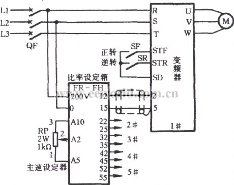
See as the figure, FR—FH is the ratio setting case, which can connect with 5 frequency converters. When more than one frequency converters need to output the ratios that are different from the main control speed, the FR-FH can set this, for example, during the progress of assembly line delivery, there are speed differences among the processes while the main speed is changeable, the connection can be done according to the figure. (View)
View full Circuit Diagram | Comments | Reading(472)
The frequency converter speed circuit with a link setting case
Published:2011/7/5 6:26:00 Author:Borg | Keyword: frequency converter, speed circuit

FR—AL is a link setting case. When the external is used to control the link of the frequency converter, the circuit shown in the figure can be adopted. In the figure, the 4-pin and 5-pin of the converter import a running signal of a 4~20mA DC, by which the rotating speed of motor M is controlled. The 4~20mA DC signal may be from the auto instrument, such as the speed sensor, mechanical sensor and so on. (View)
View full Circuit Diagram | Comments | Reading(432)
The frequency converter speed circuit with a triple speeds setting case
Published:2011/7/5 6:36:00 Author:Borg | Keyword: frequency converter, speed circuit
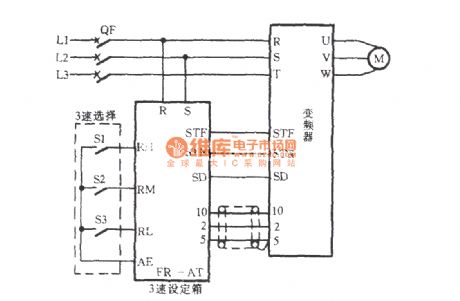
FR—AT is a triple speed setting case. When the motor M is running, different speeds are often needed at some moment, such as polishing, stirring, dehydrating, centrifuging, grinding and washing equipment and others, they often need multi-stage speeds in the processes, at this moment, the circuit in the figure can be chosen. The triple speeds selection can be done by the manual switches of S1, S2 and S3. The wire that links FR-AT to the frequency converter should be the insulated. (View)
View full Circuit Diagram | Comments | Reading(465)
| Pages:1618/2234 At 2016011602160316041605160616071608160916101611161216131614161516161617161816191620Under 20 |
Circuit Categories
power supply circuit
Amplifier Circuit
Basic Circuit
LED and Light Circuit
Sensor Circuit
Signal Processing
Electrical Equipment Circuit
Control Circuit
Remote Control Circuit
A/D-D/A Converter Circuit
Audio Circuit
Measuring and Test Circuit
Communication Circuit
Computer-Related Circuit
555 Circuit
Automotive Circuit
Repairing Circuit