Control Circuit
The door lock alarm with the time recognition function
Published:2011/7/5 8:46:00 Author:Borg | Keyword: door lock alarm, time recognition | From:SeekIC

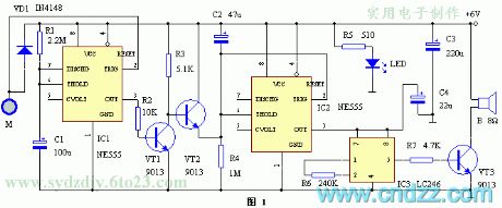
The circuit is shown in figure 1, which is composed of the 555 time-based integrated circuit and alarm integrated circuit. The time-based circuit IC1 consists of the temporary single steady trigger of T=4min or so with R1 and C1. Usually, IC1 is in the stable state, and the 3-pin of it outputs a low LEV, VT1 is blocked, VT2 is conducting, the capacitor C2 is shortened by VT2 and can't be charged, the 6-pin on the threshold of the time-based circuit IC2 is in a high LEV, while 3-pin is outputting a low LEV, the alarm sound integrated circuit IC3 is not working without power, the loudspeaker is silent. M is the touching electrode chip which is linked to the lock.
Reprinted Url Of This Article:
http://www.seekic.com/circuit_diagram/Control_Circuit/The_door_lock_alarm_with_the_time_recognition_function.html
Print this Page | Comments | Reading(3)

Article Categories
power supply circuit
Amplifier Circuit
Basic Circuit
LED and Light Circuit
Sensor Circuit
Signal Processing
Electrical Equipment Circuit
Control Circuit
Remote Control Circuit
A/D-D/A Converter Circuit
Audio Circuit
Measuring and Test Circuit
Communication Circuit
Computer-Related Circuit
555 Circuit
Automotive Circuit
Repairing Circuit
Code: