
Circuit Diagram
Index 1602
the circuit of phase-failure protector for electric motor (1)
Published:2011/6/20 8:04:00 Author:Ariel Wang | Keyword: phase-failure , protector, electric motor
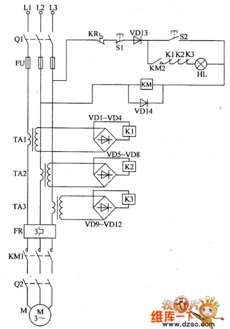
When any phase in three-phase power supply is missing because of some reason,the current transformer will lose the working current.The relay is released.The normally open contacts are disconnected.The AC contactor KM is released after power cut-off.It protects the electric motor from damage as the lose of phase.If the electric motor M is heating as the load is too heavy,the working current will increase.When the working current is beyond the set value,the thermal relay will take action.The normally closed contacts will disconnect.The AC contactor KM is released after power cut-off.Then you can cut off the working power supply of electric motor M.In order not to break down the electric motor because of overload . (View)
View full Circuit Diagram | Comments | Reading(1111)
The dual polarity input voltage/current separation amplifier circuit of transformer coupling type
Published:2011/7/4 4:01:00 Author:Borg | Keyword: dual polarity, voltage/current separation, transformer coupling

In the figure is the dual polarity input voltage/current separation amplifier circuit of transformer coupling type. In the circuit, DC/DC converter is in the same pattern with the FET chopper, the circuit adopts the analog switch 4066 to replace FET as the chopper, 4066 is connected as a bridge circuit which separates the signals by the transformer T1, as the circuits on the primary stage are the same, therefore, it has the function of dual-way input. Besides, with the positive/passive power supply driving the analog switch 4066, the forward/backward signals can be processed in the power supply voltage range.
(View)
View full Circuit Diagram | Comments | Reading(767)
The modular burglar alarm system
Published:2011/7/6 0:55:00 Author:Borg | Keyword: modular burglar alarm
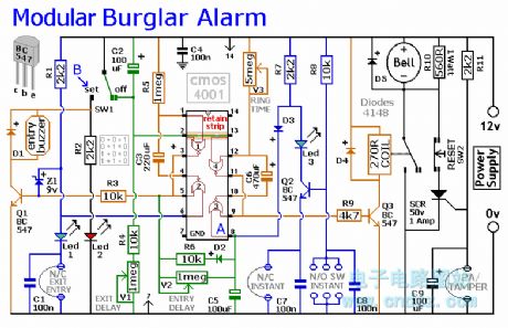
This circuit features automatic Exit and Entry delays and a timed Bell Cut-off. It has provision for both normally-closed and normally-open contacts, and a 24-hour Personal Attack/Tamper zone. It is connected permanently to the 12-volt supply and its operation is enabled by opening SW1. By using the expansion modules, you can add as many zones as you require; some or all of which may be the inertia (shock) sensor type. All the green LEDs should be lighting before you open SW1. You then have up to about a minute to leave the building. As you do so, the Buzzer will sound. It should stop sounding when you shut the door behind you. This indicates that the Exit/Entry loop has been successfully restored within the time allowed. When you re-enter the building you have up to about a minute to move SW1 to the off position. If SW1 is not switched off in time, the relay will energise and sound the main bell. It will ring for up to about 40 minutes. But it can be turned off at any time by SW1. The Instant zone has no Entry Delay. If you don't want to use N/O switches, leave out R8, C8 and Q2; and fit a link between Led 3 and C7. The 24 Hour PA/Tamper protection is provided by the SCR/Thyristor. If any of the switches in the N/C loop is opened, R11 will trigger the SCR and the bell will ring. In this case the bell has no time limit. Once the loop is closed again, the SCR may be reset by pressing SW2 and temporarily interrupting the current flow. The basic circuit will be satisfactory in many situations. However, it's much easier to find a fault when the alarm is divided into zones and the control panel can remember which zone has caused the activation. The expansion modules are designed to do this. Although they will work with the existing instant zone, they are intended to replace it. When a zone is activated, its red LED will light and remain lit until the reset button is pressed. All the modules can share a single reset button. The Stripboard layout of the prototype is available. (View)
View full Circuit Diagram | Comments | Reading(747)
The demon daming curse audio circuit of scan detection type
Published:2011/7/6 0:54:00 Author:Borg | Keyword: demon daming curse, audio circuit

See as the circuit, it includes the TWH9248/9249 radar scanning detecting/processing control coupled module, SCR lighting circuit, curse sound generating and audio power amplifier circuit and AC step-down rectifier circuit, etc, which can be used in the Buddha hall and Canon House for auto security, the aim is to fulfill the unmanned intelligent burglarproof.
(View)
View full Circuit Diagram | Comments | Reading(600)
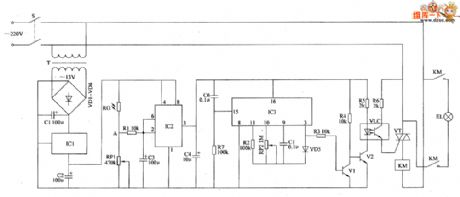
the circuit of the temperature and humidity automatic controller (2)
Published:2011/6/21 6:21:00 Author:Ariel Wang | Keyword: temperature, humidity , automatic controller
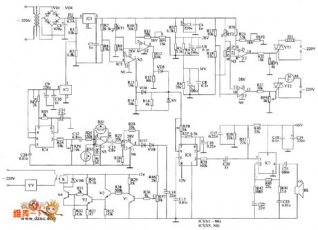
The 200V AC voltage is reduced by T,commutated by VD1~VD4,filtered by C1.Then it generates 45V DC voltage.One part of the voltage is regulated by IC1.Then it becomes +40V.It is branched by R3~R6,filtered by C5~C8.It generates +28V voltage and +16V voltage.The +28V voltage is for IC3 and IC5.The +16V voltage is for IC7.The other part of the voltage is brached by R1 and R2,regulated by C9,filtered by C10.It generates 12V DC voltage.It is the working voltage for IC4,IC6,VI~V4 and K.The +25.8V voltage is the reference voltage .It is the upper limit temperature of the temperature deviation alarm circuit.The +20V voltage is the reference voltage.It is the lower limit temperature of the temperature deviation alarm circuit. (View)
View full Circuit Diagram | Comments | Reading(531)
the circuit of the humidity controller(2)
Published:2011/6/22 7:14:00 Author:Ariel Wang | Keyword: humidity , controller
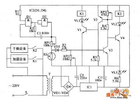
The resistence of RS changes when the humidity changes.When the environment humidity level decreases,the resistence of RS increases.The voltage of VS's base electrode increases.When the voltage of V3's base electrode is beyond 0.7V,V3 is conducted.V2 and V1 are conducted.V4 is stopped.K1 is conducted to pull in.The normally open contacts are connected.The humidifying equipment is conducted to work.At the same time,VI.1 is lighted.It indicates the humidifying equipment is working.When the humidity level increases,the resistence of RS decreases.The voltage of VS's base electrode decreases.When the voltage of Y3's base electrode is lower than 0.7V,V3 stopped.V4 is conducted.K2 is conducted to pull in.The normally open contacts are connected.The drying equipment is conducted to work.At the same time VL2 is lighted.V1 and V2 are stopped.K1 is released.
(View)
View full Circuit Diagram | Comments | Reading(440)
the automatic LED circuit of the chicken farm(3)
Published:2011/7/3 9:54:00 Author:Ariel Wang | Keyword: automatic, LED , chicken farm
When the mains switch S gets through,the 220V AC voltage is reduced by T,commutated by VD1~VD4,filtered by C1 and regulated by IC1.Then it provides +12V voltage as the working power supply for IC2.When it's dark outside,the resistence of RC is increased.The voltage from pin-2 and pin-6 of IC2 becomes low level.The in-circuit of IC2 is turned over.The pin-3 output high level.IC3 is conducted to work.The pin-3 outputs high level.V1 and V2 are conducted.The LED and the light sensitive transistor work.VT is triggered to conduct.KM is conducted to pull in.The normally open contacts are connected.EL is conducted to be lighted.
(View)
View full Circuit Diagram | Comments | Reading(493)
the circuit of fish breeding oxygen gaining controller
Published:2011/6/17 6:53:00 Author:Ariel Wang | Keyword: fish breeding, oxygen gaining, controller
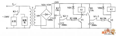
+24V voltage charges C2 by normally-closed contact R2 and K1.When the voltage of C2 reaches a certain value,transistor V1 is conducted.Relay K1 is pulled in.The normally-open contact K1-2 get through.+24V voltage charges C3 by the contacts of R3 and K1-2.At the same time,the normally-closed contact K1-1 is disconnected.C2 stops charging. The voltage of C2 discharges by R2.V1 stays conducted.K1 stays pull-in.When the voltage of C3 reaches a certain level,V2 is conducted.K2 pulls in.The normally-closed contact K2-1 is disconnected.It cuts off discharge circuit of C2.V1 stops.K1 is released.C2 starts charging again.
(View)
View full Circuit Diagram | Comments | Reading(419)
the circuit of the alarm for temperature monitor
Published:2011/6/17 8:13:00 Author:Ariel Wang | Keyword: alarm, temperature monitor
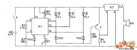
When the mains swith S gets through,battery CB provides 4.5V working power for the circuit of the whole machine.RT is used for detecting environment temperature.The resistence is decreasing when the temperature is increasin.The voltage of IC1's pin-2 is changing while the resistence of RT is changing.RP is used for setting the temperature of the monitor.When the environment temperature is right(within the set temperature) and the electric potential of IC1's pin-2 is between high level and low level.It outputs low level from pin-12.It outputs high level from pin-10 and pin-11.VL2 is lighted.VL1 and VL3 are not lighted.Sound alarming circuit does not work.HA doesn't give a sound.
(View)
View full Circuit Diagram | Comments | Reading(406)
the circuit of alarm for temperature detecting
Published:2011/6/17 23:13:00 Author:Ariel Wang | Keyword: alarm, temperature detecting
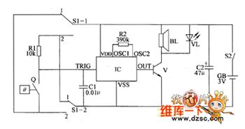
When S1 is at the position of 1 ,the alarm is being as over temperature alarm.When the controlled temperature is lower than the set temperature Q,the electrical contacts of Q are disconnected.IC stops working.BL doesn't give a sound.VL isn't lighted.When the controlled temperature is beyond the set temperature Q,the electrical contacts Q is conducted.IC is triggered to work.The acounstics signal which is output from the OUT end is amplified by V.BI gives alarm sound.VL is lighted.When S1 is at the position of 2 ,the alarm is being as low temperature alarm.When the controlled temperature is higher than the set temperature Q,the electrical contacts of Q are conducted.IC stops working.BL doesn't give a sound.VL is not lighted.
(View)
View full Circuit Diagram | Comments | Reading(460)
the circuit of loss-of-phase protecting relay for electric motor (5)
Published:2011/6/17 23:25:00 Author:Ariel Wang | Keyword: loss-of-phase, protecting, circuit , relay , electric , motor
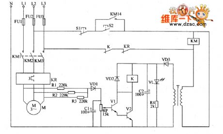
When starting button is pressed,the voltage between L2 and L3 go to AC contactor KM through Stop button 51,start push button 52 ,the normally-closed contact of relay K and contact of thermal relay KR.KM pulls in.The electric motor gets to work.It provides 12V DC voltage for relay-driven circuit(consist of V1,V2,VD2 and K) after it is reduced by T,commutated by VD3 and filtered by C2. At the same time,it lights up VL.When three-phase (L1,L2,L3) AC voltage is normal,the voltage is 0V between the plus terminal of VD1 (the Y-connected middle point) and zero line N.V1 is not conducted with V2.K is released.
(View)
View full Circuit Diagram | Comments | Reading(515)
FM transmitter 2KM circuit
Published:2011/7/6 7:03:00 Author:John | Keyword: FM transmitter
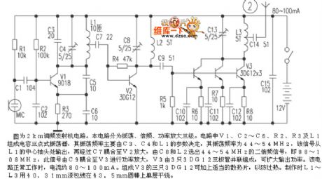
The figure shows the FM transmitter 2km circuit. The circuit is divided into three phases, which are the shock, frequency and power amplification. V1, C2 ~ C6, R2, R3, and L1 in the circuit form the three-point capacitance oscillator, whose oscillation frequency is mainly determined by parameters of the C3, C4 and L1. Its oscillation frequency is 44 ~ 54MHz. The relative signal is output from L1's center tap and then coupled to the V2 for amplification through C7. Then 44 ~ 54MHz second harmonic signal would be selected from C8 and L2, which equals to 88 ~ 108MHz. At this time, the signal is coupled to V3 power amplification through C9. And V3 is composed by three 3DG12 transistors in parallel, aiming to expand the output frequency.
(View)
View full Circuit Diagram | Comments | Reading(2435)
the circuit of phase failure protector for electric motor(3)
Published:2011/6/18 5:21:00 Author:Ariel Wang | Keyword: phase failure , protector, electric motor
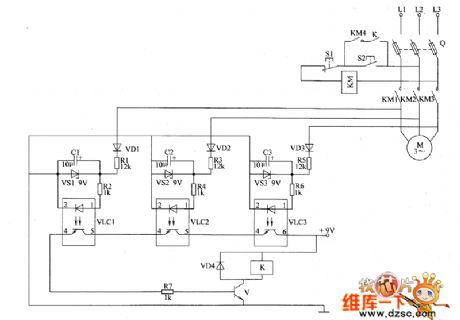
After the starting button is pressed,AC contactor KM is conducted to pull in.The normally open contacts KM1-KM4 do not get through.The electric motor M goes to work.If the three-phase AC power supply is normal,the LEDs inside VLC1-VLC3 are all lighted.The optical transistors are all conducted.V is saturated to conduct.K pulls in.The normally open contacts get through.When S2 is disconnected,KM could stay pull-in.If one of the phase in three-phase alternating-current supply is missing,the optical coupler in voltage detecting circuit is stopped.V couldn't conduct.K doesn't pull in.When S2 is disconnected,KM is no longer pull-in.The phase failure reaches the goal of automatic protection.
(View)
View full Circuit Diagram | Comments | Reading(1738)
HT0406 Single-Chip Micro-Computer Integrated Circuit
Published:2011/7/6 9:29:00 Author:Robert | Keyword: Single-Chip, Micro-Computer, Integrated


The CHT0406 is a single-chip micro-computer IC which is widely used in Konka series digital color TV sets.
The CHT0406 IC uses 42-pin dual inline package. Its internal circuit diagram and pin's functions and signal flowing is shown in picture 1. Its pin's letter code and data is listed in table 1.
The picture 1 shows the CHT0406 IC's internal circuit diagram and pin's functions and signal flowing.
The table 1 shows the CHT0406 IC's pin's letter code and data. (View)
View full Circuit Diagram | Comments | Reading(807)
Computer Protection Circuit
Published:2011/7/6 8:55:00 Author:Robert | Keyword: Computer, Protection

The computer protection circuit is shown in the picture. There are bipolar transient voltage suppression diodes VD1-VD4 connecting with the interface circuit between the computer and the peripherals. They could suppress the over-voltage pulses coming from the computer's peripheral devices. Also there are unipolar transient voltage suppression diodes VD5, VD6 separately being installed in the computer working power's input port. They could suppress the over-voltage pulses coming from the power.
The picture shows the computer protection circuit. (View)
View full Circuit Diagram | Comments | Reading(720)
KA2281 IC Internal Circuit Diagram And Typical Application Circuit
Published:2011/7/5 6:25:00 Author:Robert | Keyword: IC, Internal, Diagram, Typical, Application

The KA2281 is a LED display driving IC produced by the Korean Samsung company. It is used as the output voltage level indicator in many kinds of stereo sound systems.
The KA2281 IC has internal dual channel 5-stage LED logarithmic voltage-level indicating driving circuit. Its internal part has two inverting amplifiers and ten comparators, referenced voltage network and other circuits.
The KA2281 IC's internal circuit diagram and typical application circuit is shown in the picture. The interval of the indicating voltage level is 5dB, 5dB, 3dB, 3dB.
The picture shows the KA2281 IC's internal circuit diagram and typical application circuit. (View)
View full Circuit Diagram | Comments | Reading(8602)
CSC91330 Communication Single-Chip Micro-Computer Integrated Circuit
Published:2011/7/6 7:13:00 Author:Robert | Keyword: Communication, Single-Chip, Micro-Computer, Integrated


The CSC91330 is a communication single-chip micro-computer IC which is more used in communication equipments, such as the applications in cordless phones, corded phones, debit-card phones.
1.Its pin's functions.
The CSC91330 IC is a chip with 32-bit redialing memory function. It uses 18-pin dual in-line package and its pin's functions are listed in table 1.
The table 1 shows the CSC91330 IC's pin's functions.
2.Typical application circuit.
The control circuit typical application circuit composed of the CSC91330 IC is shown in picture 1.
The picture 1 shows the CSC91330 IC's typical application circuit. (View)
View full Circuit Diagram | Comments | Reading(740)
The integrated electric ballast circuit of R2157 straight pipe type
Published:2011/7/6 1:14:00 Author:qqtang | Keyword: electric ballast, straight pipe
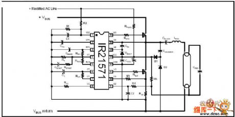
Figure: The integrated electric ballast circuit of R2157 straight pipe type (View)
View full Circuit Diagram | Comments | Reading(479)
The ChangFeng LieBao SUV engine ignition system circuit
Published:2011/7/6 1:24:00 Author:Christina | Keyword: ChangFeng, LieBao, SUV, engine, ignition system
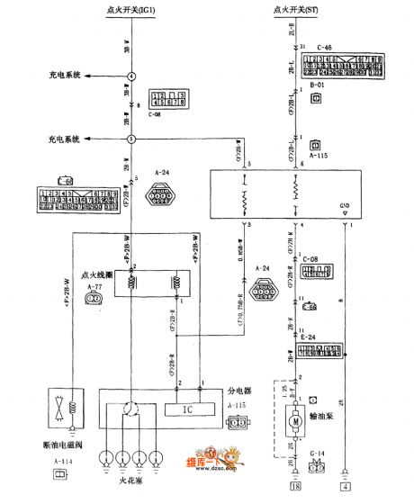
The ChangFeng LieBao SUV engine ignition system circuit:
(View)
View full Circuit Diagram | Comments | Reading(499)
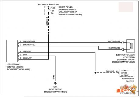
BMW electronic power steering system circuit
Published:2011/7/6 1:21:00 Author:Christina | Keyword: BMW, electronic power, steering system
View full Circuit Diagram | Comments | Reading(1018)
| Pages:1602/2234 At 2016011602160316041605160616071608160916101611161216131614161516161617161816191620Under 20 |
Circuit Categories
power supply circuit
Amplifier Circuit
Basic Circuit
LED and Light Circuit
Sensor Circuit
Signal Processing
Electrical Equipment Circuit
Control Circuit
Remote Control Circuit
A/D-D/A Converter Circuit
Audio Circuit
Measuring and Test Circuit
Communication Circuit
Computer-Related Circuit
555 Circuit
Automotive Circuit
Repairing Circuit