Automotive Circuit
the automatic LED circuit of the chicken farm(3)
Published:2011/7/3 9:54:00 Author:Ariel Wang | Keyword: automatic, LED , chicken farm | From:SeekIC

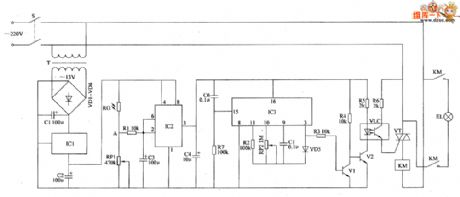
When the mains switch S gets through,the 220V AC voltage is reduced by T,commutated by VD1~VD4,filtered by C1 and regulated by IC1.Then it provides +12V voltage as the working power supply for IC2.When it's dark outside,the resistence of RC is increased.The voltage from pin-2 and pin-6 of IC2 becomes low level.The in-circuit of IC2 is turned over.The pin-3 output high level.IC3 is conducted to work.The pin-3 outputs high level.V1 and V2 are conducted.The LED and the light sensitive transistor work.VT is triggered to conduct.KM is conducted to pull in.The normally open contacts are connected.EL is conducted to be lighted.
Reprinted Url Of This Article:
http://www.seekic.com/circuit_diagram/Automotive_Circuit/the_automatic_LED_circuit_of_the_chicken_farm3.html
Print this Page | Comments | Reading(3)

Article Categories
power supply circuit
Amplifier Circuit
Basic Circuit
LED and Light Circuit
Sensor Circuit
Signal Processing
Electrical Equipment Circuit
Control Circuit
Remote Control Circuit
A/D-D/A Converter Circuit
Audio Circuit
Measuring and Test Circuit
Communication Circuit
Computer-Related Circuit
555 Circuit
Automotive Circuit
Repairing Circuit
Code: