Automotive Circuit
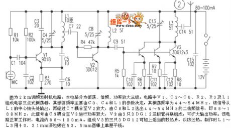
FM transmitter 2KM circuit
Published:2011/7/6 7:03:00 Author:John | Keyword: FM transmitter | From:SeekIC

The figure shows the FM transmitter 2km circuit. The circuit is divided into three phases, which are the shock, frequency and power amplification. V1, C2 ~ C6, R2, R3, and L1 in the circuit form the three-point capacitance oscillator, whose oscillation frequency is mainly determined by parameters of the C3, C4 and L1. Its oscillation frequency is 44 ~ 54MHz. The relative signal is output from L1's center tap and then coupled to the V2 for amplification through C7. Then 44 ~ 54MHz second harmonic signal would be selected from C8 and L2, which equals to 88 ~ 108MHz. At this time, the signal is coupled to V3 power amplification through C9. And V3 is composed by three 3DG12 transistors in parallel, aiming to expand the output frequency.
Reprinted Url Of This Article:
http://www.seekic.com/circuit_diagram/Automotive_Circuit/FM_transmitter_2KM_circuit.html
Print this Page | Comments | Reading(3)

Article Categories
power supply circuit
Amplifier Circuit
Basic Circuit
LED and Light Circuit
Sensor Circuit
Signal Processing
Electrical Equipment Circuit
Control Circuit
Remote Control Circuit
A/D-D/A Converter Circuit
Audio Circuit
Measuring and Test Circuit
Communication Circuit
Computer-Related Circuit
555 Circuit
Automotive Circuit
Repairing Circuit
Code: