Control Circuit
555 home appliance dual-purpose timer circuit
Published:2011/6/13 20:25:00 Author:TaoXi | Keyword: 555, home appliance, dual-purpose, timer | From:SeekIC

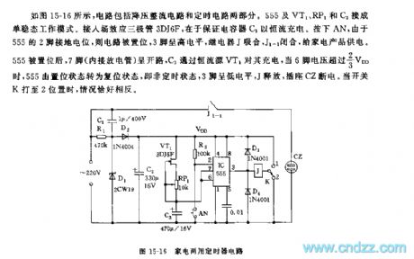
As the figure 15-16 shows, the circuit is composed of the step-down rectifier circuit and the timing circuit. The monostable operating mode is composed of the 555, VT1, RP1 and C3. You can add the field-effect transistor 3DJ6F to ensure the capacitor C3 is charged with the constant-current. If you press AN, the circuit is set because the pin-2 of 555 connects with the ground potential, pin-3 has the high electrical level, the relay J and J1-1 close to supply power to the home appliances.
After the 555 is set, the pin-7 is in the opening circuit state, C3 charges pin-7 through the constant current source VT1, when pin-6's voltage is higher than 2/3VDD, the 555 is from the set state to the reset state.
Reprinted Url Of This Article:
http://www.seekic.com/circuit_diagram/Control_Circuit/555_home_appliance_dual_purpose_timer_circuit.html
Print this Page | Comments | Reading(3)

Article Categories
power supply circuit
Amplifier Circuit
Basic Circuit
LED and Light Circuit
Sensor Circuit
Signal Processing
Electrical Equipment Circuit
Control Circuit
Remote Control Circuit
A/D-D/A Converter Circuit
Audio Circuit
Measuring and Test Circuit
Communication Circuit
Computer-Related Circuit
555 Circuit
Automotive Circuit
Repairing Circuit
Code: