Control Circuit
555 water temperature alarm circuit
Published:2011/6/13 20:26:00 Author:TaoXi | Keyword: 555, water temperature, alarm circuit | From:SeekIC

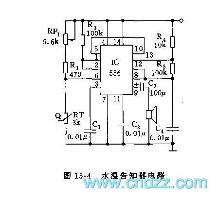
As the figure 15-4 shows, this circuit uses the 556 as the core. The monostable trigger is composed of the left part (1/2 556) of IC, the R1, R3, RP1 and the thermistor probe. The thermistor uses the resistance which has the RT=3kΩ and the negative temperature coefficient. When the water temperature is 100 degrees celsius, the resistance value is about 240Ω; when the water temperature is 50 degrees celsius, the resistance value is about 950Ω. If you pre-set the temperature and adjust RP1 to 50Ω, so the VA=RT/(RP1+R1+RT)<1/3, when the trigger port pin-6's electric potential is lower than 1/3VDD, the trigger is set, the high electrical level which is output by the pin-5 adds to the right part of the 1/2 556's reset port, f=1.44/(R4+2R5)C4, the oscillation frequency is about 1000Hz.
Reprinted Url Of This Article:
http://www.seekic.com/circuit_diagram/Control_Circuit/555_water_temperature_alarm_circuit.html
Print this Page | Comments | Reading(3)

Article Categories
power supply circuit
Amplifier Circuit
Basic Circuit
LED and Light Circuit
Sensor Circuit
Signal Processing
Electrical Equipment Circuit
Control Circuit
Remote Control Circuit
A/D-D/A Converter Circuit
Audio Circuit
Measuring and Test Circuit
Communication Circuit
Computer-Related Circuit
555 Circuit
Automotive Circuit
Repairing Circuit
Code: