Control Circuit
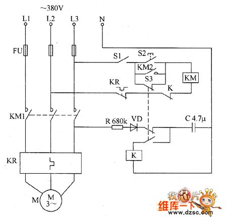
The loom electricity saving controller circuit diagarm 6
Published:2011/6/12 22:58:00 Author:Lucas | Keyword: loom , electricity saving controller | From:SeekIC

The loom electricity saving controller circuit is composed of the control switch S1, start button S2, AC contactor KM, thermal relay KR, relay K, resistor R, capacitor C, and the micro switch S3, and the circuit is shown as the chart. R uses 1W metal film resistor. C uses the oil condenser or CBB capacitor with the withstang voltage being 250V. VD uses 1N5406 silicon rectifier diode. S1 selects the 380V power switch with contact current being greater than 5A; S2 uses compression press making button; S3 selects limit switch. K selects JQX-10F 24V DC relay. KM selects the AC contact with the coil voltagein 380V, contact current capacityin 15A.
Reprinted Url Of This Article:
http://www.seekic.com/circuit_diagram/Control_Circuit/The_loom_electricity_saving_controller_circuit_diagarm_6.html
Print this Page | Comments | Reading(3)

Article Categories
power supply circuit
Amplifier Circuit
Basic Circuit
LED and Light Circuit
Sensor Circuit
Signal Processing
Electrical Equipment Circuit
Control Circuit
Remote Control Circuit
A/D-D/A Converter Circuit
Audio Circuit
Measuring and Test Circuit
Communication Circuit
Computer-Related Circuit
555 Circuit
Automotive Circuit
Repairing Circuit
Code: