Basic Circuit
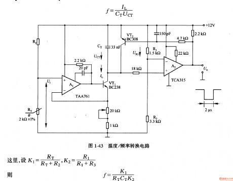
Temperature/frequency conversion circuit
Published:2011/7/5 20:22:00 Author:Lucas | Keyword: Temperature conversion, frequency conversion | From:SeekIC

In the circuit, the temperature sensor uses thermistor RT, and RT and resistor R2 form the voltage divider circuit to make resistance / temperature characteristic in linear relationship. The voltage Ui is proportional to the temperature, and it is changed into charging current IL for capacitor CT by Al and VT1. A2 could compare the voltage of URl and UCT, when UCT <URl, A2 outputs low level, VT1 is deadline, CT is charged in the current IL; when UCT ≥ UR1, A2 output is high, so that VT2 is saturated conduction, CT is discharged by VT2.
Reprinted Url Of This Article:
http://www.seekic.com/circuit_diagram/Basic_Circuit/Temperature_frequency_conversion_circuit.html
Print this Page | Comments | Reading(3)

Article Categories
power supply circuit
Amplifier Circuit
Basic Circuit
LED and Light Circuit
Sensor Circuit
Signal Processing
Electrical Equipment Circuit
Control Circuit
Remote Control Circuit
A/D-D/A Converter Circuit
Audio Circuit
Measuring and Test Circuit
Communication Circuit
Computer-Related Circuit
555 Circuit
Automotive Circuit
Repairing Circuit
Code: