Basic Circuit
Agricultural automatic water valve circuit diagram 1
Published:2011/6/18 21:56:00 Author:Lucas | Keyword: Agricultural, automatic , water valve | From:SeekIC

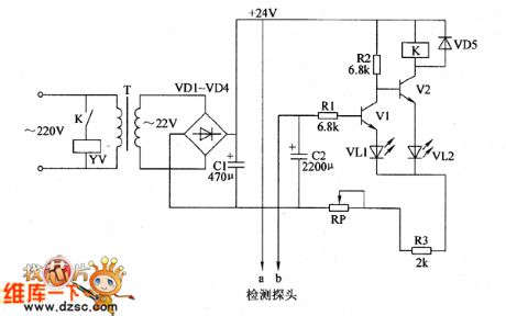
Agricultural automatic water valve circuit is composed of the power supply circuit, detection circuit and control circuit, and the circuit is shown as the Figure 1. Power supply circuit is composed of the power transformer T, rectifier diodes VD1 ~ VD4 and filter capacitor C1. The detection circuit is composed of the water level probe and resistor R3 and so on. Control circuit consists of transistors V1, V2 and the relay K and other components. AC 220V voltage is bucked by T, rectified by VD1 ~ VD4 and filtered by C1 to produce DC voltage with about 24V for the control circuit. R1 ~ R3 select 1/4W carbon film resistors. VD1 ~ VD5 select 1 N4007 silicon rectifier diodes.
Reprinted Url Of This Article:
http://www.seekic.com/circuit_diagram/Basic_Circuit/Agricultural_automatic_water_valve_circuit_diagram_1.html
Print this Page | Comments | Reading(3)

Article Categories
power supply circuit
Amplifier Circuit
Basic Circuit
LED and Light Circuit
Sensor Circuit
Signal Processing
Electrical Equipment Circuit
Control Circuit
Remote Control Circuit
A/D-D/A Converter Circuit
Audio Circuit
Measuring and Test Circuit
Communication Circuit
Computer-Related Circuit
555 Circuit
Automotive Circuit
Repairing Circuit
Code: