
Basic Circuit
Index 247
PRODUCT_DETECTOR
Published:2009/7/21 21:06:00 Author:Jessie
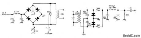
Developed for use in SSB receiver having 9-MHz IF amplifier. Values in parentheses are for receiver having 455-kHz IF amplifier. Diode types are not critical.-Circuits, 73Magazine, May 1973, p 105. (View)
View full Circuit Diagram | Comments | Reading(6594)
CONTINUOUS_DUTY_BRAKE
Published:2009/7/7 3:33:00 Author:May

High or 1 bit at output port of microprocessor energizes brake solenoid of paper-tape reader through optocoupler and amplifier,When tape is to be stopped, brake solenoid is energized and tape is squeezed between top of solenoid and flat iron brake shoe that is attracted by solenoid.-D. Hogg、The Paper Taper Caper, Kilobaud, March1977,p 34-40. (View)
View full Circuit Diagram | Comments | Reading(3863)
SSB_DETECTOR
Published:2009/7/21 22:18:00 Author:Jessie


Can be switched in and out of most tube-type AM receivers for use in place of regular detector stage Requires stable BFO.-Novice Q&A,73 Magazine, March 1977,p187. (View)
View full Circuit Diagram | Comments | Reading(740)
SIMPLE_TIME_DELAY_CIRCUIT_USING_TWO_SCRs
Published:2009/7/7 3:33:00 Author:May

View full Circuit Diagram | Comments | Reading(509)
IME_DELAY_WITH_CONSTANT_CURRENT_CHARGING
Published:2009/7/7 3:29:00 Author:May

View full Circuit Diagram | Comments | Reading(658)
HOUR_TIME_DELAY_SAMPLING_CIRCUIT
Published:2009/7/7 3:29:00 Author:May
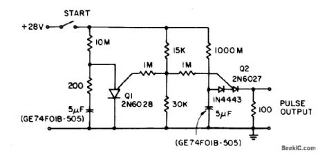

The circuit lowers the effective peak current of the output PUT, Q2. By allowing the capacitor to charge with high gate voltage and periodically lowering gate voltage, when Q1 fires, the timing resistor can be a value which supplies a much lower current than Ip. The triggering requirement here is that minimum charge to trigger flow through the timing resistor during the period of the Q1 oscillator. This is not capacitor size dependent, only capacitor leakage and stability dependent. (View)
View full Circuit Diagram | Comments | Reading(616)
ULTRA_SIMPLE_LEVEL
Published:2009/7/7 3:26:00 Author:May

This electronic level uses two LED indicators instead of an air bubble. If the surface is tilted to the right, one LED lights; if it's tilted to the left, the other LED lights. When the surface is level, both LEDs light. It uses two unidirectional mercury switches, S1 and S2. The unidirectional mercury switch has one long electrode and one short, angled electrode. The pool of mercury rides on the long electrode and makes contact between the two electrodes if the unit is held in a horizontal position. (View)
View full Circuit Diagram | Comments | Reading(507)
DIFFERENTIAL_CAPACITANCE_MEASUREMENT_CIRCUIT
Published:2009/7/7 3:25:00 Author:May

A bubble vial with external aluminum-foil electrodes is the sensing element for a simple indicating tiltmeter. To measure bubble displacement, a bridge circuit detects the difference in capacitance between the two sensing electrodes and the reference electrode. Using this circuit, a tiltmeter level vial with 2 mm deflection for 5 arc-seconds of tilt easily resolves 0.05 arc-second. The four diodes are CA3039, or equivalent. (View)
View full Circuit Diagram | Comments | Reading(1418)
DIGITAL_NOISEMAKER
Published:2009/7/7 3:25:00 Author:May

Simple sound-effect generator for video games, electronic cash registers, and electronic toys uses one-fourth of LM3900 quad opamp chip as 2-kHz signal generator that can be turned on or off by input control voltage. Suitable for applications that do not require pure sine wave. Output transistor O1, needed with low-impedance voice coil, is not critical as to type. For smaller acoustic output, Q1 can be replaced by 100-ohm resistor if 100-ohm voice coil is used, to avoid overloading IC.-T. Frederiksen, Build a Transformerless Tone Annunciator, EDN Magazine, April 5, 1977, p141-142. (View)
View full Circuit Diagram | Comments | Reading(560)
CENTIGRADE_THERMOMETER_0℃_100℃
Published:2009/7/7 3:23:00 Author:May

The ultra-low bias current of the ICL7611 allows the use of large-value gain-resistors, keeping meter-current error under 1/2%, and therefore saving the expense of an extra meter-driving amplifier. (View)
View full Circuit Diagram | Comments | Reading(456)
BASIC_DIGITAL_THERMOMETER,KELVIN_SCALE_WITH_ZERO_ADJUST
Published:2009/7/7 3:22:00 Author:May

This circuit allows zero adjustment as well as slope adjustment. The ICL8069 brings the input within the common-mode range, while the 5 k ohm pots trim any offset at 218°K (-55℃), and set the scale factor.
(View)
View full Circuit Diagram | Comments | Reading(541)
STEPPER_MOTOR_DRIVE
Published:2009/7/7 3:21:00 Author:May

Two CMOS packages provide the four feed signals required for controlling forward/reverse drive of stepper motor for carriage drive and paper advance of Bowmar Model TP 3100 thermal printer. 0ut-puts of flip-flops are above 10V, enough to drive stepper motor directly. Each clock pulse to JK flip-flop advances carriage one step in direction commanded-R Bober. Stepper Drive Circuit Simplifies Printer Control、EDN Magazine , April 5,1976,ρ114.
(View)
View full Circuit Diagram | Comments | Reading(2608)
_DIFFERENTIAL_THERMOMETER
Published:2009/7/7 3:21:00 Author:May

The 50 k ohm pot trims offsets in the devices whether internal or external, so it can be used to set the size of the difference interval. This also makes it useful for liquid-level detection (where there will be a measurable temperature difference). (View)
View full Circuit Diagram | Comments | Reading(550)
20_MHz_TONUBUS_CLOCK_PHASE_LOCK
Published:2009/7/7 3:20:00 Author:May

The 20-MHz clock phase-locks to Apple's Mac II 10-MHz NuBus clock. It uses a simple, inexpensive CMOS circuitry to generate 10- and 20-MHz square waves. The output duty cycle settings are insensitive to VCC variations. The input to the circuit is a NuBus clock signal with specifications that call for a 75 percent duty cycle at 10 MHz-a square wave that's high for 75 ns and low for the remaining 25 ns. To generate the 20-MHz signal, the circuit produces a 25-ns negative-going pulse, delayed 50 ns from the falling edge of the 10-MHz NuBus clock input at point E. NORing that pulse with the NuBus clock produces the 20-MHz clock at point G. Finally, applying the 25-ns pulse to the set input of a set-reset input, results in a 10-MHz square wave at F.
(View)
View full Circuit Diagram | Comments | Reading(509)
ELECTRONIC_THERMOMETER
Published:2009/7/7 3:19:00 Author:May

An inexpensive electronic thermometer is capable of measuring temperatures over a range of from -30°F to + 120°F. A diode-connected 2N3904 transistor used as the temperature sensor forms a voltage divider with RI. As temperature increases, the voltage drop across the transistor changes by approximately -1.166 millivolts-per°F. As a result, the current at pin 3 of IC1, a 741 op amp with a gain of 5, decreases as the temperature measured by the sensor increases.A second 741 op amp, IC2 is configured as an inverting amplifier. Resistors R5 and R6 calibrate the circuit. Calibration is also straightforward. When properly done, a temperature of -30°F will result in a meter reading of 0 milliamps, while a temperature of 120°F will result in a meter reading of 1 milliamp. Divide the scale between those points into equal segments and mark the divisions with the appropriate corresponding temperatures. The calibration is completed by placing the sensor in an environment with a known temperature, such as an ice-point bath. Place the sensor in the bath and adjust R6 until you get the correct meter reading. (View)
View full Circuit Diagram | Comments | Reading(5144)
SIX_TONE_CHIME_
Published:2009/7/7 3:18:00 Author:May

Separate AF oscillators, gated on by six-stage time-delay circuit, generate six different chime tones. Loudspeakers can be mounted so each tone comes from different location in house. When doorbell button is pushed, each tone generator is turned on in sequence for period determined by individual time controls. System operates from 9-V battery, with CMOS logic drawing very little standby current.-J. Sandier, 9 Projects under $9, Modern Electronics, Sept. 1978, p 35-39. (View)
View full Circuit Diagram | Comments | Reading(1776)
REMOTE_THERMOMETER
Published:2009/7/7 3:18:00 Author:May

The low output impedance of a closed loop op amp gives ideal line-noise immunity, while the op amp's offset voltage drift provides a temperature sensor. Using the op amp in this way requires no external components and has the additional advantages of a hermetic package and unit-to-unit mechanical uniformity if replacement is ever required.The op amp's offset drift is amplified to drive the meter by the LTC1052. The diode bridge connection allows either positive or negative op amp temperature sensor offsets to interface directly with the circuit. In this case, the circuit is arranged for a + 10℃ to +40℃ output, although other ranges are easily accommodated. To calibrate this circuit, subject the op amp sensor to a +10℃ environment and adjust the 10℃ trim for an appropriate meter indication. Next, place the op amp sensor in a +40℃ environment and trim the 40' adjustment for the proper reading. Repeat this procedure until both points are fixed. Once calibrated, this circuit will typically provide accuracy within ±2℃, even in high noise environments. (View)
View full Circuit Diagram | Comments | Reading(578)
DIGITAL_THERMOCOUPLE_THERMOMETER
Published:2009/7/7 3:16:00 Author:May

This digital thermocouple thermometer uses one active component and 15 passive components. With this circuit, both type J and type K thermocouples may be used. The type J will measure over the temperature range of 10 to 530℃ with a conformity of ±2℃. The type K will measure over a temperature range of 0℃ to 1000℃ with a conformity of ±3℃. (View)
View full Circuit Diagram | Comments | Reading(3190)
DIGITAL_THEREMIN
Published:2009/7/7 3:15:00 Author:May

The CD4069 or 74C04 hex inverter-is used as a fixed-frequency oscillator centered around 100 kHz. U2 contains the variable frequency oscillator and balanced modulator.The CD4046 is a phase-locked loop and R3, R4, and C2 determine the center frequency of the on-chip oscillator. The antenna forms a parallel capacitance with C2, which allows the frequency to be shifted several kilohertz by bringing a hand near the antenna. R4, the ZERO control, allows the variable oscillator to be set to the same frequency as the fixed oscillator. When the difference frequency is below 15 Hz, it is below the lower frequency limit of the ear. By setting both oscillators to the same frequency, the Theremin remains silent until the performer brings his or her hand near the antenna. The oscillators are mixed by an exclusive OR gate inside the 4046. That gate acts as a digital balanced modulator, which produces the sum and difference frequencies. The output of the gate is then ac coupled by C3 to LEVEL control R5 and an output jack for connection to an audio amplifier or stereo receiver.
(View)
View full Circuit Diagram | Comments | Reading(3130)
SPARE_FLIP_FLOP_INVERTER
Published:2009/7/7 3:14:00 Author:May

The circuit uses one-half of a dual D flip-flop as an inverter. When the input decreases, the flip-flop resets, and its Q output increases. When the input increases, the reset line is released and Q gets clocked low. The rc delay between applying the input signal to the flip-flop's reset input and its clock input enables clocking the flip-flop on the input's positive edge. A 74HC74 dual D flip-flop, for example, requires a minimum recovery time of 5 ns after releasing the reset input before strobing its clock input. Therefore, speccing rc at greater than 7.5 ns provides adequate margin. The slight slowing of the clock edge presents no problem, because the clock input's maximum allowable rise time is a much longer 500 ns. To prevent skewing of the output's symmetry, limit the maximum input frequency to less than 10 MHz.
(View)
View full Circuit Diagram | Comments | Reading(681)
| Pages:247/471 At 20241242243244245246247248249250251252253254255256257258259260Under 20 |
Circuit Categories
power supply circuit
Amplifier Circuit
Basic Circuit
LED and Light Circuit
Sensor Circuit
Signal Processing
Electrical Equipment Circuit
Control Circuit
Remote Control Circuit
A/D-D/A Converter Circuit
Audio Circuit
Measuring and Test Circuit
Communication Circuit
Computer-Related Circuit
555 Circuit
Automotive Circuit
Repairing Circuit