
Index 398
MAX752 application circuit
Published:2011/6/14 2:40:00 Author:Christina | Keyword: application circuit
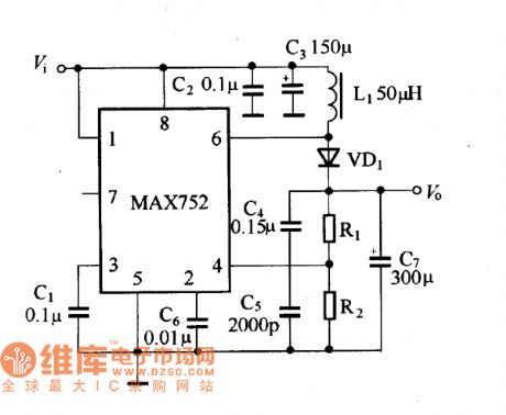
The MAX752 application circuit is as shown in the figure. In this figure, C2 must be close to the chip, this can inhibit the high voltage which is caused by the load fluctuation.
MAX752 application circuit (View)
View full Circuit Diagram | Comments | Reading(450)
A0C56A1125-33 color displayer single chip microcomputer integrated circuit
Published:2011/6/24 7:49:00 Author:Christina | Keyword: color displayer, single chip, microcomputer, integrated circuit
The A0C56A1125-33 is designed as one kind of color displayer single chip microcomputer integrated circuit that can be used in the domestic and imported brands of color displayers such as the TongFang series.etc.
1.Features
The A0C56A1125-33 is composed of the clock oscillating circuit, the reset control circuit, the memory circuit, the I(2)C bus control circuit, the S correction control circuit, the indicator light control circuit, the static noise control circuit, the boot/standby control circuit, the line and field synchronous signal processing circuit, the rotary control circuit, the X-ray detection signal processing circuit and other subsidiary function circuits.
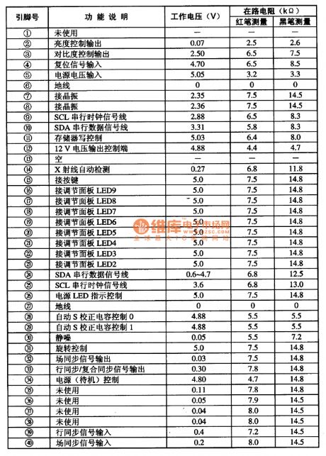
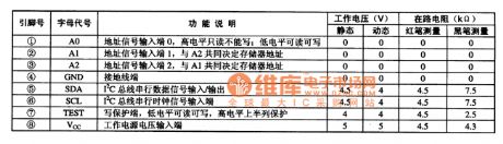
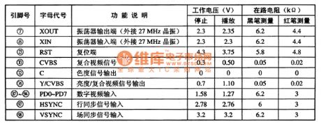
2.Pin functions and data
The A0C56A1125-33 uses the 40-pin dual-row DIP package, the pin functions and data are as shown in table 1.
Table 1 The pin functions and data of the A0C56A1125-33
(View)
View full Circuit Diagram | Comments | Reading(414)
UC1846 typical application circuit
Published:2011/6/21 1:09:00 Author:Christina | Keyword: typical application
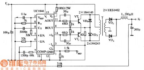
The dual-port output push-scratching type switching voltage regulator, it has the features of excellent performance and low cost.
UC1846 typical application circuit (View)
View full Circuit Diagram | Comments | Reading(1510)
AT24C04 memory integrated circuit
Published:2011/6/24 7:42:00 Author:Christina | Keyword: memory, integrated circuit
The AT24C04 series memory integrated circuit can be used with the single-chip microcomputer, the stored information is different according to the occasions.
1.Features
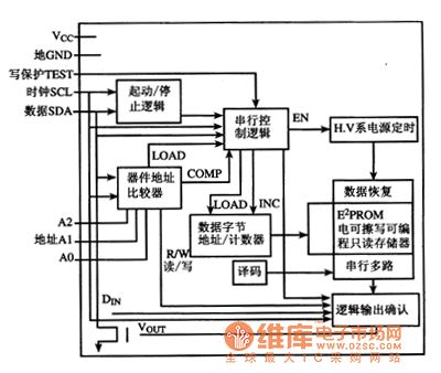
The AT24C04 is composed of the I(2)C bus circuit, the E(2)PROM electric erasable programmable read-only memory (ROM), the data byte address/counter circuit.etc. The internal circuit block diagram is as shown in figure 1.
Figure 1 The internal circuit block diagram of the AT24C04
2.Pin functions and data
The AT24C04 uses the 8-pin dual-row DIP package, the pin functions and data are as shown in table 1, this data is measured from the ChangHong CH-10 large screen color TV.
Table 1 The pin functions and data of the AT24C04
(View)
View full Circuit Diagram | Comments | Reading(775)
AV1428 digital audio and video processing integrated circuit
Published:2011/6/24 7:31:00 Author:Christina | Keyword: digital, audio, video, processing, integrated circuit
The AV1428 is designed as one kind of digital audio and video processing integrated circuit that is produced by the Panasonic company, it can be used in various brands of DAD, VCD players such as the WanLiDa and the Desay series.
1.Features
The AV1428 is composed of the NTSC/PAL digital video coding circuit, three 9-bit video DAC and PLL clock synchronous circuits, the audio DAC and audio digital processing circuit. It can be used to change the decompressed video data code signal into the video signal, and it changes the audio data into the analog audio signal.
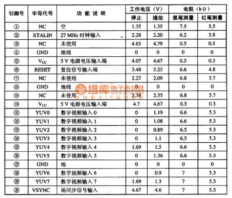
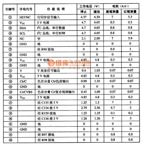
2.Pin functions and data
The AV1428 uses the 100-pin square package, the pin functions and data are as shown in table 1.
Table 1 The pin functions and data of the AV1428
(View)
View full Circuit Diagram | Comments | Reading(424)
AV3169 digital video coding integrated circuit
Published:2011/6/24 7:20:00 Author:Christina | Keyword: digital, video, coding, integrated circuit
The AV3169 is designed as one kind of digital video coding integrated circuit that is produced by the Panasonic company, and it can be used in various brands of DAD, VCD players.
The AV142 integrated circuit is composed of the clock oscillating circuit, the digital video processing circuit, the I(2)C bus interface circuit, the bright color processing circuit.etc. It uses the 44-pin square package, the pin functions and data are as shown in table 1.
Table 1 The pin functions and data of the AV142
(View)
View full Circuit Diagram | Comments | Reading(425)
The BA3101 fan single chip microcomputer integrated circuit
Published:2011/6/23 6:45:00 Author:Christina | Keyword: fan, single chip, microcomputer, integrated circuit
The BA3101 is designed as one kind of fan single chip microcomputer integrated circuit which is produced by the Toyo company, and it can be used in all kinds of fan control program circuits.
1.Features
The BA3101 is composed of the time base circuit, the key instruction decoder circuit and other kind of control circuit.
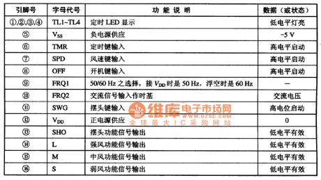
2.Pin functions and data
The BA3101 uses the 16-pin dual-row DIP package, the pin functions and data are as shown in table 1.
Table 1 The pin functions and data of the BA3101
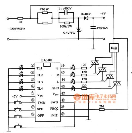
3.Typical application circuit
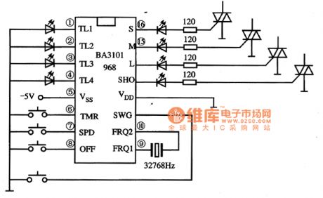
The fan program control system typical application circuit is as shown in figure 1.In order to improve the accuracy and stability of the timing, we usually use the external crystal method which is as shown in figure 2.
Figure 1 The typical application circuit of BA3101
Figure 2 The external crystal method
(View)
View full Circuit Diagram | Comments | Reading(569)
AY-3-8600 single chip game console integrated circuit
Published:2011/6/23 8:14:00 Author:Christina

The AY-3-8600 is designed as one kind of single chip game console integrated circuit that can be used to form the toy game circuit.
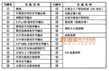
1.Pin functions
The AY-3-8600 uses the 28-pin dual-row package, the pin functions are as shown in table 1. It is composed of the signal mixing circuit, the clock generator circuit and the reset circuit.etc.
Table 1 The pin functions of the AY-3-8600 integrated circuit
2.Typical application circuit
The game console typical application circuit which is composed of the AY-3-8600 integrated circuit is as shown in figure 1.
Figure 1 The typical application circuit of the AY-3-8600
(View)
View full Circuit Diagram | Comments | Reading(2552)
AX5112 fan single chip microcomputer integrated circuit
Published:2011/6/24 7:12:00 Author:Christina | Keyword: fan, single chip, microcomputer, integrated circuit
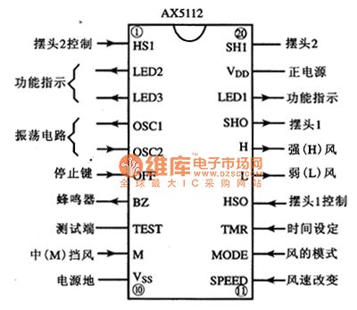
The AX5112 is designed as one kind of fan single chip microcomputer integrated circuit which is produced by the ASL company, and it can be used in various kinds of fan program control circuits.
1.Pin functions
The AX5112 uses the 20-pin dual-row DIP package, the pin functions is as shown in figure 1.
Figure 1 The pin functions of the AX5112
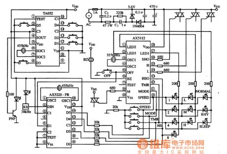
2.Typical application circuit
The remote control fan's typical application circuit which is composed of the AX5112 is as shown in figure 2.
Figure 2 The typical application circuit of the AX5112
(View)
View full Circuit Diagram | Comments | Reading(499)
Biological taking poison device circuit diagram 3
Published:2011/6/18 22:50:00 Author:Lucas | Keyword: Biological , taking poison device
The biological taking poison device circuit is composed of the power supply circuit, multivibrator and output circuit, and the circuit is shown in Figure 37. Power supply circuit consists of the power switch S, battery GB, current limiting resistor R1 and the power indicator light-emitting diode VL. Multivibrator is composed of the capacitors C1, C2, resistor R2, potentiometer RP1 and time-base integrated circuit IC. Output circuit is composed of the pulse transformer T, potentiometer RP2, voltmeter N and electrodes A, B. R1 and R2 use the l/4W carbon film resistors or metal film resistors. RP1 uses the WH series of small synthetic membrane switch potentiometer without switch; RP2 uses the WH series of small synthetic carbon film potentiometer with switch.
(View)
View full Circuit Diagram | Comments | Reading(475)
Biological taking poison device circuit diagram 2
Published:2011/6/18 22:45:00 Author:Lucas | Keyword: Biological , taking poison device
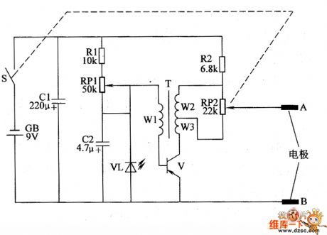
The biological taking poison device circuit is actually low-frequency oscillator circuit which is composed of the transistor V, pulse transformer T and the realted external components, and the circuit is shown in the chart. Adjusting the resistance of RP1 can change the working frequency of low-frequency oscillator. Regulation the resistance of RP2 can change the output pulse voltage amplitude (ie, the intensity of electrical pulses). R1 and R2 select 1/4W gold film resistors. RPI uses WH-15 series of small synthetic membrane potentiometer without switch; RP2 uses WH-15 series of small synthetic carbon film potentiometer with switch. C1 and C2 select the aluminum electrolytic capacitor with the voltage in 16V. VL chooses Φ3mm red light-emitting diode.
(View)
View full Circuit Diagram | Comments | Reading(407)
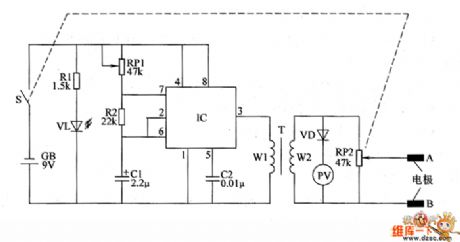
Biological taking poison device circuit diagram 1
Published:2011/6/18 22:39:00 Author:Lucas | Keyword: Biological, taking poison device
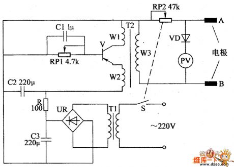
Biological taking poison device circuit is composed of the power supply circuit, self-excited intermittent oscillator and output circuit, and the circuit is shown in the chart. Power supply circuit is composed of the power switch S, power transformer T1, bridge rectifier UR, filter capacitors C2, C3 and current limiting resistor R. Self-excited intermittent oscillator is composed of the capacitor C1, potentiometer RP1, transistor V, the windings W1, W2 of pulse transformer T2. Output circuit is composed of the winding W3 of pulse transformer T2, potentiometer RP2, diodes VD, voltmeter PV and electrodes A, B. Adjusting the RP1 resistance can change the frequency of self-excited intermittent oscillator.
(View)
View full Circuit Diagram | Comments | Reading(471)
Electric arc welding generator
Published:2011/6/19 2:46:00 Author:Lucas | Keyword: Electric arc welding , generator

The maximum input of the circuit shown as the chart is less than 100W, and it uses the weak current arc technology to automatically ignite quickly about 5mm ~ 10mm, l ~ 3A stable arc. It is used as DC arc welding machine, which can improve arc welder success rate from 30% to l00% to solve the arc problem. The electric arc is difficult to extinguish, and arc welding does not occur the same piece stick welding. The device itself can also be used as a pocket-sized welder to do the welding of lmm metal shell, wire, capillaries, joints and so on.
(View)
View full Circuit Diagram | Comments | Reading(5147)
The wiring diagram of DS8 100V,5A universal inducted three-phase three-wire meter
Published:2011/6/20 5:24:00 Author:Lucas | Keyword: wiring diagram , 100V, 5A , universal , inducted , three-phase, three-wire, meter
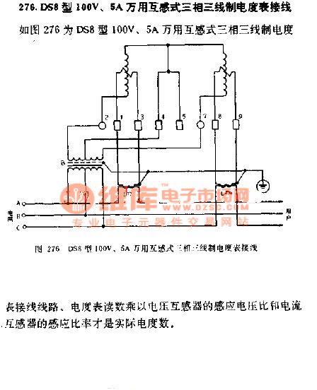
The wiring diagram of DS8 100V,5A universal inducted three-phase three-wire meter is shown as the chart. The meter reading multiplied by the induced voltage ratio of voltage transformer and induced ratio of current transformer is the actual kWh.
(View)
View full Circuit Diagram | Comments | Reading(913)
Wiring diagram of DX8 100V,5A universal inducted three-phase three-wire 60 °no-power meter
Published:2011/6/20 5:34:00 Author:Lucas | Keyword: Wiring diagram , 100V, 5A, universal , inducted , three-phase, three-wire , 60°, no-power, meter
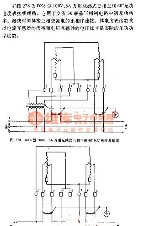
Wiring diagram of DX8 100V,5A universal inducted three-phase three-wire 60 °no-power meter is shown as the chart 278.It is used to adjust the reactive power of AC 50HZ three-phase system circuit. The wiring is actual connected according to the positive phase sequence of three-phase AC. The meter reading multiplied by the ratio of current transformer and the voltage ration of voltage transformer is the actual reactive power degree.
(View)
View full Circuit Diagram | Comments | Reading(954)
The wiring diagram of MF52 multimeter
Published:2011/6/20 6:03:00 Author:Lucas | Keyword: wiring diagram , multimeter
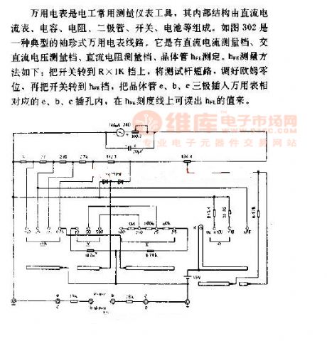
Multimeter is usual a instrument tool for electrician, and its internal structure is composed of the DC ammeter, capacity,resistor, diode, switch, battery. Figure 302 is a typical pocket multimeter lines. It tested by DC current measurement file, AC voltage measurement file, DC resistor measurement file, the transistor hfE. HfE measurement method is shown as follow: the switch is turned the R × 1K file and the stick gage is in the short circuit, then the zero ohms shold be adjusted. Then the switch is turned to hfE file, and the e, b, c poles of transistor are connected to the corresponding to e, b, c jacks of meter.
(View)
View full Circuit Diagram | Comments | Reading(540)
LM161, LM1261, LM1361 high-speed complementary output voltage comparator
Published:2011/6/21 5:23:00 Author:Lucas | Keyword: high-speed, complementary , output , voltage comparator
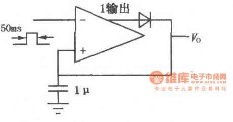
LM161/261/361 has high transmission speed, common power supply voltage, independent strobe terminal, and it has two low delay complementary TTL outputs, low input offset voltage. When the circuit is driving , the switching speed is small, and it ises double in-line package. The circuit shown as the chart is the high-speed peak detector.
(View)
View full Circuit Diagram | Comments | Reading(621)
LM139, LM239, LM339 low-power low offset voltage comparator
Published:2011/6/21 5:15:00 Author:Lucas | Keyword: low-power, low offset , voltage comparator
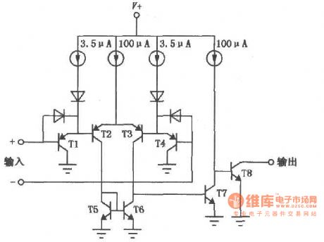
LM139/239/339 is a widely used voltage comparator with excellent performance. It has the features of low power consumption, low offset current, low bias current, and it can supplied by a single power supply, and its output end is compatible with a variety of logic circuits(TTL / DTL / ECL / MOS / CMOS), and each package has four independent comparators. The internal block circuit diagram:
(View)
View full Circuit Diagram | Comments | Reading(1110)
LM119/219/319 double-precision voltage comparator
Published:2011/6/21 6:19:00 Author:Lucas | Keyword: double-precision, voltage comparator
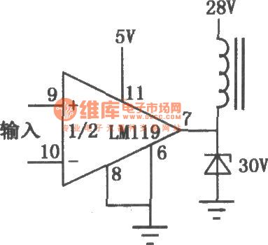
Each package of LM119/219/319 has two separate comparators, which can be supplied by a single 5V power supply. It has high conversion speed, low input bias current, and the output section has a separate ground leading terminal, and the output is compatible to TTL / RTL / DTL capacitors. LM119/219/319 has the high sensitivity, which can be used to compare the the weak signals. It is the precision voltage comparator with higher output power, and it is widely used in control, measurement and other electronic systems. The circuit shown as the chart is the driving relay circuit.
(View)
View full Circuit Diagram | Comments | Reading(544)
AM685 ultra-high-speed voltage comparator
Published:2011/6/21 6:14:00 Author:Lucas | Keyword: ultra-high-speed, voltage comparator
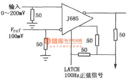
AM685 has a complementary ECL output signal and 5012 linear drive capability; it uses the dual in-line multi-layer metal hermetic package. AM685 is widely used in automatic control, precision instruments and other electronic systems, and high-speed pulse modulator is shown as the chart.
(View)
View full Circuit Diagram | Comments | Reading(808)
| Pages:398/471 At 20381382383384385386387388389390391392393394395396397398399400Under 20 |
Circuit Categories
power supply circuit
Amplifier Circuit
Basic Circuit
LED and Light Circuit
Sensor Circuit
Signal Processing
Electrical Equipment Circuit
Control Circuit
Remote Control Circuit
A/D-D/A Converter Circuit
Audio Circuit
Measuring and Test Circuit
Communication Circuit
Computer-Related Circuit
555 Circuit
Automotive Circuit
Repairing Circuit