
Index 382
AC current / voltage conversion circuit
Published:2011/7/5 7:36:00 Author:Lucas | Keyword: AC , current / voltage conversion

The circuit uses CT current converter, and the first level of flows the measured current, then the secondary level could get the AC voltage being proportional to the input current. When the measured AC current wire crosses the ring core CT, due to the magnetic field changes generate inducing voltage on the two ends of coil, and the higher current frequency will result higher induced voltage. Low-frequency characteristics of coil depends on the load resistors R1 and RP1, RP2, which are used to adjust the switching sensitivity. If using RP1 and RP2 to do interaction adjustment, it will make the circuit have flat frequency characteristics.
(View)
View full Circuit Diagram | Comments | Reading(7294)
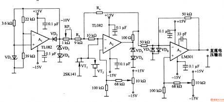
Triangle / sine wave converter circuit
Published:2011/7/5 7:08:00 Author:Lucas | Keyword: Triangle / sine wave converter

This is the approximate polygonal circuit, which could change the sine wave in triangular wave, and it is widely used in the sine function generator. In the circuit, VTl-VT4 are used as power circuit of VD6, VDl2, and the voltage changes with temperature, then V is available as a sensor to detect the ambient temperature. RP1 and RP2 could adjust the positive and negative voltage. For reducing distortion, they should be interactive adjusted to make high-order harmonic distortion in 0.2% to 0.5% . VT5 and VT6 are the push-pull buffer amplifiers with the load impedance in lkΩ. For driving 500 load, it should be added the broadband amplifier with four times gain.
(View)
View full Circuit Diagram | Comments | Reading(7500)
Current / frequency conversion circuit composed of MAX471
Published:2011/7/5 20:12:00 Author:Lucas | Keyword: Current conversion, frequency conversion
The circuit input current range is lO0mA to lA, and the output frequency is proportional to the input current. In the circuit, MAX471 is the high-end current detection integrated circuit, and the ratio between output current and load current is 1:2000. If the load current is lA, the output current is 0.5 mA. When MAX471 output is in high level, it will charge for Cl, and charging voltage rises in slash. MAX952 is a versatile integrated circuit chip, which includes the 1.2 V reference voltage (accuracy is 2%), comparator, operational amplifier and so on.
(View)
View full Circuit Diagram | Comments | Reading(481)
Isolated current / frequency conversion circuit
Published:2011/7/5 20:36:00 Author:Lucas | Keyword: Isolated , current conversion , frequency conversion
The circuit uses the high noise isolation circuit to play a role of isolation, and it will convert current into 0-IOkHz frequency, which is output by the optical coupler TLP521. The circuit iscomposed of the voltage ratio and current / voltage conversion parts. LM331 voltage frequency could convert the voltage into frequency; current / voltage conversion uses the resistor Rl to generate the voltage at both ends (1-5V), and it is converted into 0 -10V voltage by Al (gain is set to 2.5 times). (View)
View full Circuit Diagram | Comments | Reading(486)
Current/frequency conversion circuit
Published:2011/7/5 8:28:00 Author:Lucas | Keyword: Current/frequency conversion
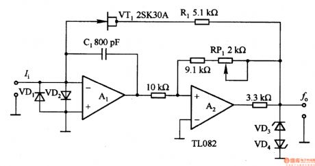
In the circuit, Al is integral circuit. When it has the current input, the integrator capacitor integrates to a negative direction. A2 output voltage is clamped by regulator diodes VD3 and VD4, so Al is inverted when the output is about -5 · 6V, after VTl is turned on, the integral voltage outputs rapidly until being inverted at +5 · 6V. Al output rising time depends on the clamping voltage, resistor Rl and the integrating capacitor Cl, and reducing the input current Ii and Cl time constant can decrease the rising time. Oscillation frequency is mainly decided by the input current and C1.
(View)
View full Circuit Diagram | Comments | Reading(1144)
Resistance/voltage transform circuit
Published:2011/7/5 8:21:00 Author:Lucas | Keyword: Resistance/voltage transform
This circuit is actually a resistance meter, which can directly indicate resistance. A2 is an inverting amplifier, and Rx is connected in the feedback loop. If the offset voltage and input bias current source can be ignored, the A2 output voltage U. =- UR (Rx / Rs), and it can find Rx = Rs /-URo to select the reference resistor Rs to get a fixed reference voltage, then the output voltage U. is the measured resistance, which can be directly read out. Rs is divided in the range of 2OOΩ -2MΩ with the unit in 10 times, and converted into 0-2V voltage output.
(View)
View full Circuit Diagram | Comments | Reading(548)
High output voltage/current conversion circuit
Published:2011/7/5 20:30:00 Author:Lucas | Keyword: High output , voltage conversion, current conversion

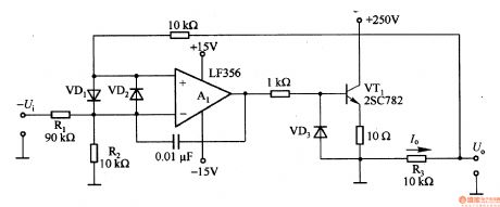
The circuit uses the floating ±15V +250 V power supply to get load voltage which is greater than 2OOV. Input voltage U is 0 -lOV, which could be 0-1V divided by R1 and R2. It is assumed that Al inverting input voltage is -lV, the ground potential is a benchmark, the Al output is placed forward and VTl has base current flowing, so the output end voltage increases, then current f. = LV/R3 through the load. When I. R3 =- lV, the loop is stable, if R3 changes in the range of 0.1 - lOkΩ, it can be converted into the current with the range of lOmA to l0OμA .
(View)
View full Circuit Diagram | Comments | Reading(600)
Temperature/frequency conversion circuit
Published:2011/7/5 20:22:00 Author:Lucas | Keyword: Temperature conversion, frequency conversion
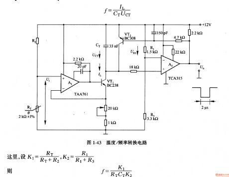
In the circuit, the temperature sensor uses thermistor RT, and RT and resistor R2 form the voltage divider circuit to make resistance / temperature characteristic in linear relationship. The voltage Ui is proportional to the temperature, and it is changed into charging current IL for capacitor CT by Al and VT1. A2 could compare the voltage of URl and UCT, when UCT <URl, A2 outputs low level, VT1 is deadline, CT is charged in the current IL; when UCT ≥ UR1, A2 output is high, so that VT2 is saturated conduction, CT is discharged by VT2.
(View)
View full Circuit Diagram | Comments | Reading(531)
Voltage / current and current / voltage conversion circuit composed of NJM4558
Published:2011/7/5 20:06:00 Author:Lucas | Keyword: Voltage / current, current / voltage , conversion
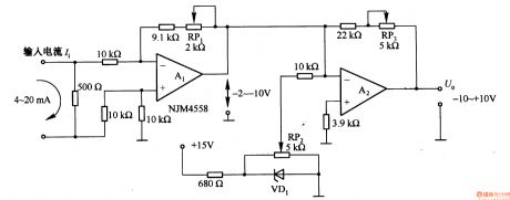
Figure 1-42 (a) is a voltage / current conversion circuit, and it can convert 0-lOV input voltage into 4-2OmA output current. Adjusting RP2 could make Ui = 0, I. = 2OmA; adjusting RP2 could make Ui = lOV, I. = 4mA. Figure 1-42 (b) is the current / voltage conversion circuit, which will convert the 4-2OmA current into -10 to + lOV output voltage. Adjusting RP1 could make the A1 output -2 to -lOV; adjusting RP3 could make the A2 output -10 to +10 V; adjusting RP1 could make the bias voltage of A2 in +6 V.
(View)
View full Circuit Diagram | Comments | Reading(5264)
Midea household automatic dishwasher circuit
Published:2011/6/23 20:49:00 Author:TaoXi | Keyword: Midea, household, automatic dishwasher

The working principle of the dishwasher: the dishwasher uses the electrical motor to drive the wash pump to form the water with 3m injection pressure, the water is pressured by the wash pump and is heated by the heating tube, then it is jetted by the blowhole of the sprinkler. Because the reaction force of the water spray adds to the sprinkler to make it to turn constantly, this makes the water column which is sprayed on the top of the dishwasher to have the large recoil force, the spray arm constantly sprays the hot-water which has the detergent or bleaching lotion on the tableware surface from the three-dimensional direction densely.
(View)
View full Circuit Diagram | Comments | Reading(1606)
Resistance/voltage transform circuit composed of TL082
Published:2011/7/5 8:33:00 Author:Lucas | Keyword: Resistance/voltage transform
Al and VD1 constitute constant current source circuit, and Al outputs a constant output voltage, which is the key of resistance/voltage transform circuit, and it can transform -lOV reference voltage into current by reference resistance (R (RP1)+ R1). Since (R (RP1) + R1) resistance is lOkΩ, -lOV reference voltage can get lmA reference current. lmA base current flowing through resistor RX is converted into a corresponding voltage, which is output by buffer amplifier A3, then it will convert resistor RX to the corresponding voltage. In the circuit, the VD3-VD8 and VTl, VT2 constitute a protection circuit.
(View)
View full Circuit Diagram | Comments | Reading(3603)
Agricultural automatic water valve circuit diagram 1
Published:2011/6/18 21:56:00 Author:Lucas | Keyword: Agricultural, automatic , water valve
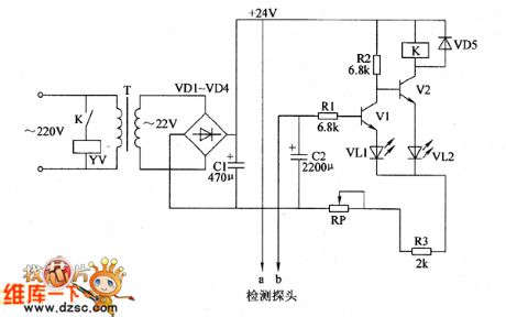
Agricultural automatic water valve circuit is composed of the power supply circuit, detection circuit and control circuit, and the circuit is shown as the Figure 1. Power supply circuit is composed of the power transformer T, rectifier diodes VD1 ~ VD4 and filter capacitor C1. The detection circuit is composed of the water level probe and resistor R3 and so on. Control circuit consists of transistors V1, V2 and the relay K and other components. AC 220V voltage is bucked by T, rectified by VD1 ~ VD4 and filtered by C1 to produce DC voltage with about 24V for the control circuit. R1 ~ R3 select 1/4W carbon film resistors. VD1 ~ VD5 select 1 N4007 silicon rectifier diodes.
(View)
View full Circuit Diagram | Comments | Reading(711)
Electric sewing machine no-load economizer circuit diagram 2
Published:2011/6/30 5:27:00 Author:Lucas | Keyword: Electric , sewing machine , no-load , economizer

The electric sewing machine no-load economizer circuit is composed of low-voltage circuit breaker QF, control switch S1, light switches S2 and S4, foot switch S3, AC contactor relay KM and time relay KT, and the circuit is shown as the chart. When the sewing workers continue to work, then move the clutch pedal to turn off S3, KT gets power and resets, KM gets power and pulls in, then M starts running, and they begin sewing work. If it needs lighting during the M stopped time, you can manually turn on light switch S2, the EL light will be lit. S1, S2 use the self-locking power switches with the contact current being more than 5A; S3 uses the protected move off button. KM selects the AC contactor with the coil voltage in 220V, contact current in 10A.
(View)
View full Circuit Diagram | Comments | Reading(2400)
MAX866 converter, main features and pin of power supply monitor
Published:2011/7/4 22:33:00 Author:Lucas | Keyword: converter, main features , pin , power supply monitor
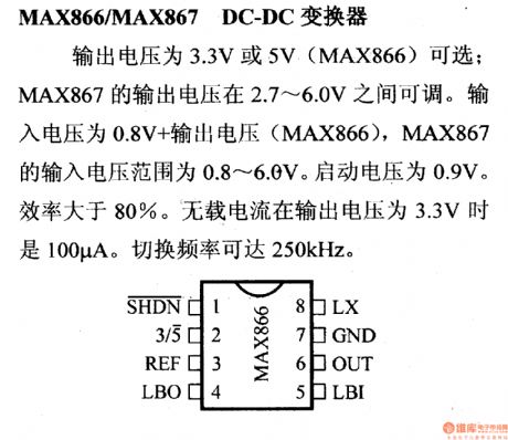
MAX866/MAX877DC-DCconverter
Output voltage is 3.3V or 5V (MAX866) ; MAX867's output voltage is adjustable between 2.7 ~ 6.0V. Output voltage is 0.8V, MAX866's output voltage range is 0.8 ~ 6.0V. Starting voltage is 0.9V. Efficiency is greater than 80%. No-load current is 100μA when the output voltage is 3.3V. Switching frequency is up to 250KHZ.
(View)
View full Circuit Diagram | Comments | Reading(476)
Automatic switching circuit of voltage and current control mode
Published:2011/7/4 22:12:00 Author:Lucas | Keyword: Automatic , switching , control mode
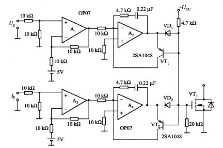
Al and A2 form the voltage control mode, and Us is the load output voltage detection signal, A3 and A4 constitute the current control mode, and IS is the load current detection signal. The circuit can switch automatically according to the voltage and current detection signals. For example, in the voltage control range, the VD1 conduction, VT1 does not work. Then the output of A4 increases, if it reaches the base current level of VT2, the VT2 conduction, then the A4 is added negative feedback by VT2.
(View)
View full Circuit Diagram | Comments | Reading(2960)
The power MOSFET isolated gate drive circuit
Published:2011/7/4 22:10:00 Author:Lucas | Keyword: MOSFET , isolated gate , drive circuit

In the circuit, the pulse signal of input A and input B is from the TL494 or UC3852 switching power supply integrated controller. T1 and T2 are the pulse transformers, which aim for high-voltage isolation and to enhance the noise immunity to make high power switching circuit work reliably. The duty cycle range of the circuit is 0% to 45%. Power MOSFET switching characteristics are related to gate driving capacity, here VT3 and VT4 use PNP transistors.
(View)
View full Circuit Diagram | Comments | Reading(5888)
Power MOSFET gate drive circuit composed of transistor
Published:2011/7/4 22:08:00 Author:Lucas | Keyword: Power MOSFET gate , drive circuit , transistor

The circuit consists of two forward converters: one is the charging converter for power MOSFET gate capacitor; the other is discharging converter gate for the gate capacitor. Recommended power supply voltage is 12 to 15V. On the rising edge of the drive pulse, VT5 receives pulse, for the figure given the values of Cl and Rl, the typical duration time is 2OOns, and the pulse is transmitted to the secondary stage of transformer Tl. When VT6 and VD3 are in the appropriate offset, the secondary pulse will charge for the gate - source capacitor of driven power MOSFET, then shut down the current path.
(View)
View full Circuit Diagram | Comments | Reading(7891)
Three-Point Protection Circuit
Published:2011/7/5 5:58:00 Author:Robert | Keyword: Three-Point, Protection

The three-point protection circuit is shown in the picture. When there is a surge voltage flowing into the circuit, the gas discharge tube would guide the surge current to the underground. So that the equipments could get the protective effects.
The picture shows the three-point protection circuit. (View)
View full Circuit Diagram | Comments | Reading(641)
Fluorescent lamp driver circuit composed of FET
Published:2011/7/4 23:42:00 Author:Lucas | Keyword: Fluorescent lamp , driver circuit , FET

Fluorescent tube is connected in the LC resonant circuit composed of L2 and C9. Bidirectional breakdown diode VD4 is starting circuit. When AC power is connected, VT2 gate potential increases by VD4; when the voltage exceeds the gate threshold voltage, VT2 is conducted. Thus, the resonant current folws C8, fluorescent wire, resonant capacitor C9, choke L2, the winding of drive transformer Tl by +25 V DC voltage, and the oscillation cycle is decided by C9, L2, and T1. Before the light iturning on, the resonant state is decided by the C9, L2, and VT1, VT2. (View)
View full Circuit Diagram | Comments | Reading(3187)
The lamp drive circuit using NE555
Published:2011/7/5 1:15:00 Author:Lucas | Keyword: lamp , drive circuit
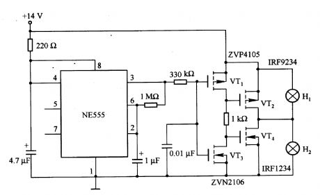
In the circuit, the bulb Hl and H2 are connected in parallel. When Hl is lit; MOSFET tube VT4 is conducted, almost all the supply voltage is added at both ends of H1, then Hl is brightest. For lighting the bulb H2, t, it will generate 3Oms delay, then the end of bulb has been lit by filament light bulb, and the impact is that the impulse current is limited to be the steady-state current of lamp to extend lamp life. NE555is the oscillator circuit, andthe pin 3 outputs pulse signal.
(View)
View full Circuit Diagram | Comments | Reading(2452)
| Pages:382/471 At 20381382383384385386387388389390391392393394395396397398399400Under 20 |
Circuit Categories
power supply circuit
Amplifier Circuit
Basic Circuit
LED and Light Circuit
Sensor Circuit
Signal Processing
Electrical Equipment Circuit
Control Circuit
Remote Control Circuit
A/D-D/A Converter Circuit
Audio Circuit
Measuring and Test Circuit
Communication Circuit
Computer-Related Circuit
555 Circuit
Automotive Circuit
Repairing Circuit