
Index 399
LM111, LM211, LM311 single voltage comparator
Published:2011/6/21 6:11:00 Author:Lucas | Keyword: single, voltage comparator
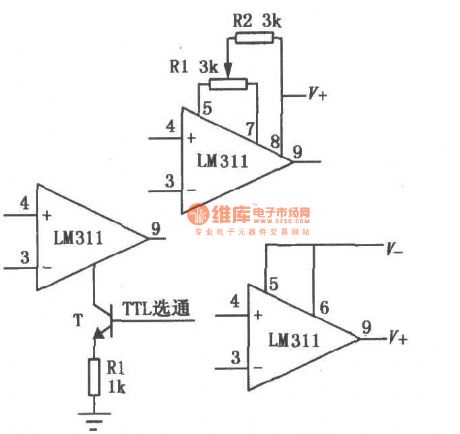
LM111/211/311 supply voltage range (± 5V ~ ± l5V) is high; bias current is low; offset current is low; differential input voltage range (± 30V)is high, and its output is compatible to TTL, DTL and MOS circuit, and it can drive LED and relay. The circuit can use single power supply or dual power supply, and it has two forms of collector output and emitter output. This comparator also has the external balance adjustment and strobe control terminals, which can be used according to choice or adjustment. The basic use of the circuit is shown as the chart.
(View)
View full Circuit Diagram | Comments | Reading(2165)
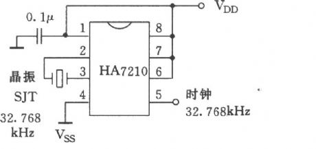
The application circuit of HA7210 programmable crystal oscillator
Published:2011/6/20 8:27:00 Author:Lucas | Keyword: application circuit , programmable, crystal oscillator
View full Circuit Diagram | Comments | Reading(524)
The TA7344P typical application circuit
Published:2011/6/23 20:30:00 Author:Seven | Keyword: typical application
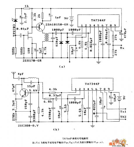
Figure:The TA7344P typical application circuit
Notes: Trl is the high LEV or low LEV output (V&H, V&L); Tx2 is the manifier output(V6(p,P)). (View)
View full Circuit Diagram | Comments | Reading(538)
The electrocardiogram amplifier ECG circuit
Published:2011/6/17 23:58:00 Author:Seven | Keyword: electrocardiogram amplifier
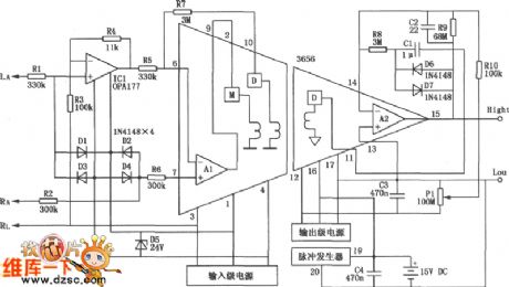
The electrocardiogram amplifier ECG circuit is shown in the figure, apart from the transformer coupling separation amplifier3656, it is also fixed with a precise computer OPA177 (the offset volatge is ≤10μV, and the drifting is 0.1μV/℃, the open loop gain is higher than 130dB, the dynamic typical current is 1.5mA), its aim is to use to high impedance input difference instrument amplifier composed of the input stage op-amp AI in OPA177 in 3656. CAD is a common disease, as the living rhythm is fastening, the living standard and health consciousness are strengthened. (View)
View full Circuit Diagram | Comments | Reading(1700)
The LM555 wide dynamic pulse width modem design circuit
Published:2011/6/18 2:34:00 Author:Seven | Keyword: dynamic pulse width, modem design circuit
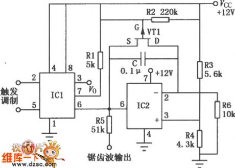
The LM555 wide dynamic wide modem design The LM555 wide dynamic wide modem is mainly composed of the integrated timer and the integrator circuit. As it is fixed with a computing amplifier, the temperature stability is good and the linear dynamic range is wide, the minimum width of its output pulse is 2μs and the maximum is 6ms, the max/min is 300:1. As the modulating input signal is changing, the output pulse width is also changing accordingly, so that the pulse width is adjusted, at the same time, the sawtooth wave voltage signal is launched.
(View)
View full Circuit Diagram | Comments | Reading(554)
The KJT1 adjustment control board circuit principle diagram
Published:2011/6/18 2:48:00 Author:Seven | Keyword: adjustment control board, principle diagram
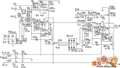
The KJT1 adjustment control board circuit principle diagram with graph paper.The KJT1 adjustment control board consists of the 2-stage computing amplifier, which has the proportional integral sector circuit and a speed dual closed-loop system. This PI adjustment board can work with KJZ2, KJZ3 , KIz6 and other controllable silicon distribution boards, it can fulfill functions of single phase, 3-phase AC voltage adjustment, speed adjustment or AC voltage adjustment and speed adjustment. It has a good quality and convenient usage. The KJTI adjustment control board circuit is shown in the figure.
(View)
View full Circuit Diagram | Comments | Reading(726)
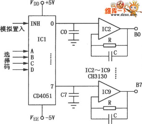
The CD4051 and CH3130 multi-channel demodulator circuit
Published:2011/6/18 2:55:00 Author:Seven | Keyword: multi-channel demodulator
View full Circuit Diagram | Comments | Reading(1521)
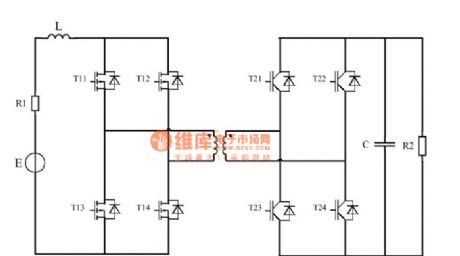
The dual-way DC/DC converter circuit
Published:2011/6/14 4:22:00 Author:Borg | Keyword: dual-way, DC/DC converter
View full Circuit Diagram | Comments | Reading(436)
The precise rectifier circuit with the integrating sub-circuit
Published:2011/6/19 3:36:00 Author:Seven | Keyword: precise rectifier, integrating sub-circuit
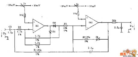
This circuit can switch the input DC signal into the DC signal. If the input signal is in a very low frequency, the input terminal capacitor C1 can be omitted.
In the forward half-cycle, the output terminal of op-amp IS1 is connected by diode D1, and it is separated in the same phase by D2. The op-amp IS2 is working as the inverting voltage follower. In the backward half-cycle, IS1 is the phase inverter and it is connected with the summing point by R2. On the input terminal, R3 and R2 compose a passive feedback circuit. (View)
View full Circuit Diagram | Comments | Reading(568)
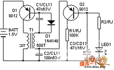
the simple LED driver circuit
Published:2011/6/19 8:56:00 Author:Seven | Keyword: LED driver
View full Circuit Diagram | Comments | Reading(734)
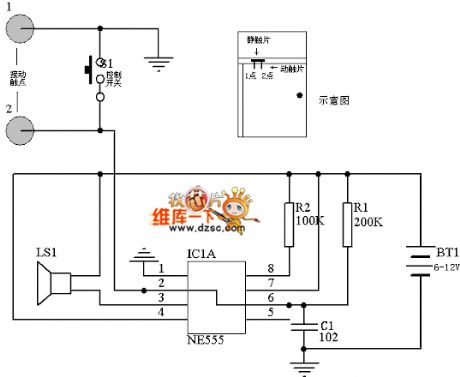
Broken line alarm production circuit diagram
Published:2011/6/14 3:46:00 Author:Lucas | Keyword: Broken line , alarm, production
View full Circuit Diagram | Comments | Reading(580)
The Shanghai Passat basic circuit
Published:2011/6/19 20:40:00 Author:qqtang | Keyword: Passat, basic circuit
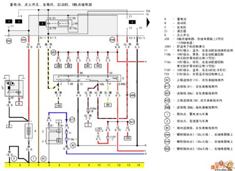
The flash mode connection circuit is shown in the figure.
(View)
View full Circuit Diagram | Comments | Reading(411)
CEC910 fan single chip microcomputer integrated circuit
Published:2011/6/13 4:56:00 Author:Christina | Keyword: fan, single chip, microcomputer, integrated circuit
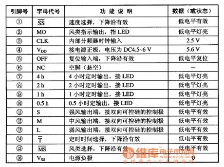
The CEC910 is designed as one kind of fan single chip microcomputer integrated circuit, and it can be used in the speed regulation or the power regulation applications of the fan and all sorts of small home appliances.
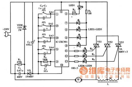
The CEC910 is in the 16-pin dual-row DIP plastic package, the pin functions and data is as shown in the table 1, the typical application circuit is as shown in figure 1.
Table 1 The pin functions and data of the CEC910
Figure 1 The typical application circuit of the CEC910
(View)
View full Circuit Diagram | Comments | Reading(520)
The TC9149P/TC9150F typical application circuit
Published:2011/6/20 21:21:00 Author:Seven | Keyword: application circuit
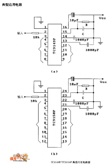
Figure: The TC9149P/TC9150F typical application circuit (View)
View full Circuit Diagram | Comments | Reading(709)
The MCl45436 typical application circuit
Published:2011/6/20 1:36:00 Author:Seven | Keyword: typical application circuit
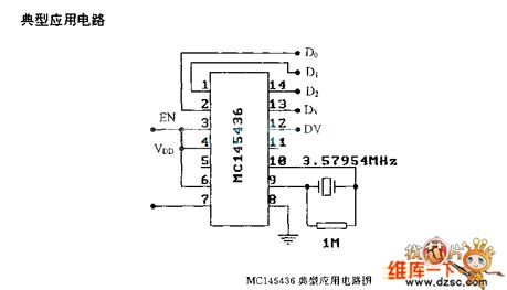
Figure: The MCI45436 (general) logic frame circuit (View)
View full Circuit Diagram | Comments | Reading(452)
The MCl45436 (general) logic frame circuit
Published:2011/6/20 1:38:00 Author:Seven | Keyword: logic frame circuit

The MCl45436 (general) logic frame circuit (View)
View full Circuit Diagram | Comments | Reading(401)
Agricultural automatic water valve circuit diagram 2
Published:2011/6/16 3:57:00 Author:Lucas | Keyword: Agricultural , automatic , water valve
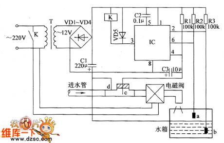
The agricultural automatic water valve circuit is composed of the power supply circuit, detection circuit and control circuit, and the circuit is shown as the Figure 1. Power supply circuit is composed of the power transformer T, rectifier diodes VD1 ~ VD4 and filter capacitor C1 and so on. Detection circuit is composed of the high water level detection electrode a, low water level detection electrode b and water inlet pipe detection electrode c and so on. Control circuit consists of the time-base integrated circuit IC, relay Κ and the external components. R1 ~ R3 use 1/4W or 1/8W metal film resistors. VD1 ~ VD5 use 1N4001 or 1N4007 silicon rectifier diodes.
(View)
View full Circuit Diagram | Comments | Reading(632)
Agricultural automatical water feeder circuit diagarm 18
Published:2011/6/14 5:58:00 Author:Lucas | Keyword: Agricultural , automatical water feeder
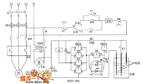
The agricultural automatical water feeder circuit is composed of the power supply circuit, water level detection control indicating circuit, starter control circuit, and the circuit is shown as the chart 1. Power supply circuit is composed of the power transformer T, bridge rectifier and filter capacitor C. The water level detection control indicating circuit consists of water level detection electrodes a ~ c, six NOT gate IC IC (D1 ~ D6), resistors R1, R2, relay K, color light-emitting diode VL and diode VD. The starter control circuit is composed of the knife switch Q, fuses FU1 ~ FU3, power switch S1, manual / automatic control switch S2, stop button S3, start button S4, AC contactor KM and thermal relay ER.
(View)
View full Circuit Diagram | Comments | Reading(436)
Agricultural automatical water feeder circuit diagarm 17
Published:2011/6/16 5:28:00 Author:Lucas | Keyword: Agricultural , automatical , water feeder

The agricultural automatical water feeder circuit is composed of the power supply circuit, bistable circuit and water level measurement and control circuit, and the circuit is shown as the Figure 1. Power supply circuit is composed of the power transformer T, bridge rectifier UR, filter capacitors C1, C2, and three-terminal voltage regulator integrated circuit IC. Bistable circuit consists of transistors V2, V3 and the external components. Water level measurement and control circuit consists of transistors V1, V4, Reed A, Reed B, and resistors R1, R2, R6 ~ R8, R14 and so on. R1 ~ R14 use 1/4W carbon film resistors or metal film resistors. VD1 and VD2 use 1N4148 silicon switch diodes.
(View)
View full Circuit Diagram | Comments | Reading(401)
Agricultural automatical water feeder circuit diagarm 16
Published:2011/6/14 5:53:00 Author:Lucas | Keyword: Agricultural , automatical water feeder
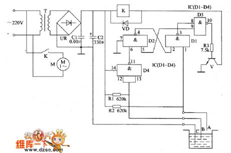
The agricultural automatical water feeder circuit is composed of the power supply circuit and water level detection control circuit, and the circuit is shown as the chart 1. Power supply circuit is composed of the power transformer T, bridge rectifier UR and filter capacitors C1, C2. Water level detection control circuit is composed of the water level detection electrodes A ~ C, four NAND gates integrated circuit IC (D1 ~ D4), transistor V, resistors R1 ~ R3, relay K and diode VD. AC 220V voltage is bucked by T , rectified by UR and filtered by C1, C2 to provide 12V voltage for relay K and IC. R1 ~ R3 use the carbon film 1/4W resistors or metal film resistors.
(View)
View full Circuit Diagram | Comments | Reading(417)
| Pages:399/471 At 20381382383384385386387388389390391392393394395396397398399400Under 20 |
Circuit Categories
power supply circuit
Amplifier Circuit
Basic Circuit
LED and Light Circuit
Sensor Circuit
Signal Processing
Electrical Equipment Circuit
Control Circuit
Remote Control Circuit
A/D-D/A Converter Circuit
Audio Circuit
Measuring and Test Circuit
Communication Circuit
Computer-Related Circuit
555 Circuit
Automotive Circuit
Repairing Circuit