
Index 401
Typical Applied Circuit of M50560-200P IC
Published:2011/5/16 2:42:00 Author:Michel | Keyword: IC, Applied Circuit

Typical Application Circuit
The remote control applied circuit composed of M50560-200P IC is showed as the picture.
Picture:Typical Application Circuit of M505060-200P IC (View)
View full Circuit Diagram | Comments | Reading(1499)
Typical Application Circuit of M5060-O1P IC
Published:2011/5/16 7:13:00 Author:Michel | Keyword: Application Circuit

Typical Application Circuit
Remote-control emitter typical appliction circuit composed of M50560 IC is showed as above.
Picture:Typical Application Circuit of M5060-O1P IC (View)
View full Circuit Diagram | Comments | Reading(708)
Inner Circuit Pane Circuit of M50560-01P IC
Published:2011/5/18 2:32:00 Author:Michel | Keyword: Inner Circuit Pane, Circuit, IC

Functions and FeaturesM50560一01P contains color periodic circuit,teleswitch command encoder timing signal generator,key sweep gate generator,code element modulator,buffer and other accessory circuit.Its inner circuit pane picture is showed as above.Picture:Inner Circuit Pane Circuit of M50560-01P IC (View)
View full Circuit Diagram | Comments | Reading(870)
Typical Application Circuit of M54060 IC
Published:2011/5/17 3:38:00 Author:Michel | Keyword: Typical Application Circuit


Typical Application Circuit
The remote control applied ciruit composed of M50460 IC is showed as above.
Picture:Typical Application Circuit of M50460 IC (View)
View full Circuit Diagram | Comments | Reading(707)
Typical Application Circuit of M50142P IC
Published:2011/5/18 2:28:00 Author:Michel | Keyword: Typical Application Circuit, IC

Typical Application Circuit
Typical Application circuit of infrared remote control composed of IM50142P IC is showed as above.Picture:Typical Application Circuit of M50142P IC
Notice:This circuit is the original picture of remote control infrared-emitter so the resistor sign hasn't been modified.
Note:VT01and VT02 are direct coupling system drive circuits.Supply voltage reachs the groundafter it passesinfrared-emitting diode,VD01, and resistance, RO4, when VT02 tube short-circuits.At this time,infrared-emitting diode shines but without any information in infrared light so the remote control is invalid. (View)
View full Circuit Diagram | Comments | Reading(856)
crystal diode DDZX9698TS internal circuit
Published:2011/5/31 7:47:00 Author:chopper | Keyword: crystal diode, internal

View full Circuit Diagram | Comments | Reading(342)
electronic sound modeling mouse expeller circuit
Published:2011/6/10 7:15:00 Author:chopper | Keyword: electronic, sound modeling, mouse expeller
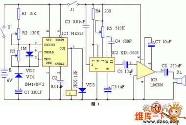
The principle of circuit is shown as picture 1.It is formed by time control circuit,meows generation circuit,power amplification circuit and so on.Time control circuit is formed by time base circuit IC1 NE555 and its peripheral resistance-capacitance component,diode.It is a impulse oscillator of adjustable dutyfactor,and its dutyfactor is controlled by R2 and R3.Meows generation circuit is formed by a CMOS integrated circuit IC2 KD-5605 and fixes meows in inner circuit by using storage technology. (View)
View full Circuit Diagram | Comments | Reading(655)
crystal diode DDZX9701TS internal circuit
Published:2011/6/1 2:07:00 Author:chopper | Keyword: crystal diode, internal
View full Circuit Diagram | Comments | Reading(342)
Three-phase electromotor low-speed operation circuit
Published:2011/6/1 21:12:00 Author:Christina | Keyword: Three-phase, electromotor, low-speed, operation

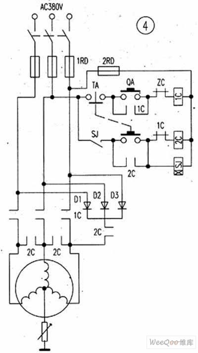
The Three-phase electromotor low-speed operation circuit is as shown:
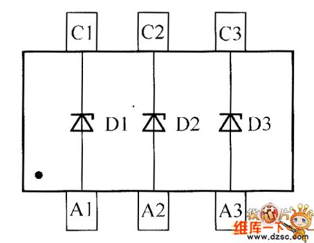
Some times we need the electromotor to work in the low-speed operation state, and we do not want to use the mechanical reducer, so we can use this circuit to achieve. As the figure shows, we connect the VD1~VD3 with the three-phase winding in series, and add the normally open contact point KM2 to the three-phase winding, then we press ST1, KM1 will close, VD1, VD2 and VD3 connect with the winding, the electromotor M will operate in the low-speed state. IF we press ST2, KM2 closes to short connect the VD1, VD2 and VD3, the electromotor M will run at full speed with the rated voltage. (View)
View full Circuit Diagram | Comments | Reading(637)
Water level indicator circuit (5)
Published:2011/6/7 6:13:00 Author:Christina | Keyword: Water level, indicator

The water level indicator uses the LED to indicate the three stages water level of high, medium and low, and it can be used in wide range of water level indication applications such as the water tank, the pool, the boiler and the underground wells.
The circuit working principle: the water level indicator is composed of the water level electrodes A-D, the resistors Rl-R6, the capacitors Cl-C3, the time base circuits ICI-IC3 and the LEDs VLl-VL3, as the figure shows.
When there is no water in the tank, the +6V voltage adds to the pin-2 and pin-6 of the ICl-IC3 getsthrough Rl-R3, so pin-2 and pin6 have the high electrical level, pin-3 of ICl-IC3 output the low electrical level, VLl-VL3 will not turn on.
(View)
View full Circuit Diagram | Comments | Reading(1760)
Digital tube dynamic scanning circuit
Published:2011/5/25 21:40:00 Author:Christina | Keyword: Digital tube, dynamic scanning
One group of digital tube dynamic scanning display needs two groups of control signal: one group is the font code which is output by the field output port, this font code can be used to control the displaying font, called the segment-code, another group is the control signal which is output by the bit output port, this control signal can be used to select which bit of the digital tube will be working, called the bit-code.
The digital tube is composed of seven bar-type LEDs and a circular LED, so there are 8 section lines that can be used in the 8-bit parallel system. There are two kinds of digital tubes: the altogether cathode and the altogether anode. The public cathode of the altogether anode digital tube connects to the ground.
(View)
View full Circuit Diagram | Comments | Reading(501)
Photoflash Circuit
Published:2011/6/3 12:51:00 Author:Michel | Keyword: Photoflash Circuit

The photoflash circuit is showed as above.
The seagulls SD - 150 type studio flash combines formative light and photography intense light source also accompanied by advanced synchronous remote control device of inside light modulation,which makes many electronic umbrella lamp also flash to achieve much light shooting effect.K1 is power switch,K2 is weak light switch of model lamp,K3 isstrong light switch of model lamp,S1 is flash trigger button,S2 is optical synchronous flash interface ,S3 is camera synchronous flash interface. (View)
View full Circuit Diagram | Comments | Reading(3595)
Basic Circuits of Switching Power AC Input and Commuted Filter
Published:2011/6/6 23:29:00 Author:Michel | Keyword: Switching Power, AC Input, Commuted Filter, Basic Circuits
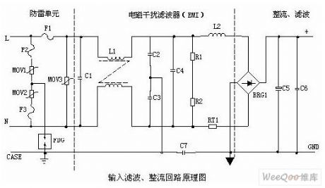
①Lightning protection circuitThe circuit composed of MOV1,MOV2,MOV3(F1、F2、F3、FDG1 ) protects the whole circuit when there is lightning and produced voltage leads in the power supply via power system.When the two terminals' voltgae of RPS is more than its work voltage ,its resistance magnitude drops to make high voltage energy consume on RPS.F1,F2,F3 will be burnt to protect next circuit if the current is excessive.②Input filter circuitDouble π type filtering network composed of C1,L1,C2 and C3 mainly prevents electromagnetic noises of input source and clutter signals to avoid the power supply being obstructed.Meanwhile,it also prevents that high frequency clutter generated by the power supply itself disturbs electrified wire netting. (View)
View full Circuit Diagram | Comments | Reading(507)
Optically Coupled High-side Driving Circuit of Improved Double Power
Published:2011/6/10 6:55:00 Author:Michel | Keyword: Improved Double Power, Optically Coupled, High-side, Driving Circuit
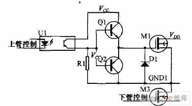
In the abboved double power coupling tube drive circuit scheme,using the copling output direct driving circuit makes the output waveform deformated seriously.Especially the falling edge of the waveform is slower, this is mainly caused by the capacitance between the MOS tube's G and S'level. The capacitance between G and s will be charged when the output waveform is high electricity ,which makes the wavefrom rise slightly slow.The capacitance between G and s will be discharged via R1 when the output waveform turns lower,which makes electric potential of MOS tube's G stage drop slowly and the wavform deformates seriously.It's impossible to remove the capacitance between G and s,we improve the mentioned driving project,according to pulling driving circuit on the thread on singlechip mouth and the imroving project is showed as above. (View)
View full Circuit Diagram | Comments | Reading(452)
Four-way Output Decoding Multiplex Converting Circuit of D-A Converter
Published:2011/6/10 4:52:00 Author:Michel | Keyword: D-A Converter, Four-way Output, Decoding, Multiplex Converting Circuit
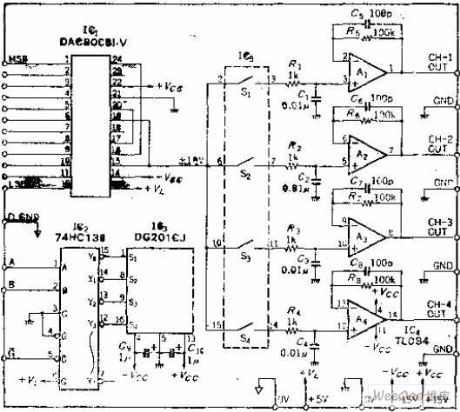
Circuit's Functions
Many A-D converters will be used when many analog switchers are connected to input ports,they are switching in multiplex ways and the channels' scanning are slow.This circuit is contrast,it changes a D-A converter into four ways output, constitutes four equivalent D-A converters,and it is used in the D-A output conversion speed slow circuit, which can reduce the cost.
Circuit's Work PrincipleAbout this circuit's work principle,it's easy to understand as long as you think of that 4 rotary switchs are connected to D-A converter's output port and the rotating shaft is whirling in high speed. (View)
View full Circuit Diagram | Comments | Reading(780)
Unijunction Transistor Constitutive Thyristor Trigger Circuit
Published:2011/6/4 22:12:00 Author:Michel | Keyword: Unijunction Transistor, Thyristor Trigger Circuit
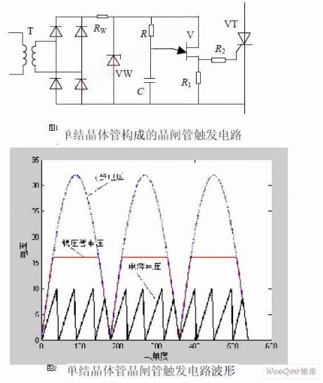
The thyristor trigger circuit composed of unijunction transistor is showed as the picture 1 and its voltage waveform is showed as the picture.Compared with relaxation oscillation circuit composed of unijunction transistor,the oscillating parts are same.Synchronous can be realized through improving power circuit.Sinusoidal alternating current bucks when it passes through the synchronous transformer T,changes into low ac voltage and then it changes into pulsing dc when it goes through diode rectifier bridge. The voltage regulator tube VW and resistor,RW's function is to clip and VW is off when pulsating voltage is lower than voltage regulator tube's voltage and both terminals' voltage is equal to rectifier output voltage. (View)
View full Circuit Diagram | Comments | Reading(788)
Circuit of Sawtooth Wave Generator with Constant Current Charging
Published:2011/6/4 1:31:00 Author:Michel | Keyword: Constant Current, Charging Sawtooth Wave Generator

Capacitor charging has almost nothing to do with collector voltage when the strong feedback transistor T is used.The required sawtooth wave amplitude can be gotten when R1 is changed.The collected current can be altered when R3 is changed to regulate frequency.Conversing capacitor value can change frequency in a wider range. (View)
View full Circuit Diagram | Comments | Reading(2278)
Trapezoidal Wave Generator Circuit
Published:2011/6/4 2:10:00 Author:Michel | Keyword: Trapezoidal, WaveGenerator Circuit
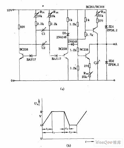
The trapezoidal wave generator showed as the picture(b) can be output when the picture (a) circuit is used.The trapezoidal wave's time t1 ~ t2 can be adjusted independently.Time T1 regulates via regulating capacitor C1 crudely,potentiometer fine respectivly.t2 is adjusted via regulating capacitor C2 crudely ,RP2 fine respectivly.t1+t2 fix the cycle or frequency.t3's change depends on potentiometer RP3 and its value is calculated as t3=CRE·UA/UE.Here RE is total PNP transistor shot extremel resistance, UE is emitter drop,UA is output voltage amplitude. (View)
View full Circuit Diagram | Comments | Reading(1598)
Triangle Wave - Rectangle Wave Generator Circuit
Published:2011/6/4 2:26:00 Author:Michel | Keyword: Triangle Wave, Rectangle Wave, Generator Circuit

This circuit is composed of three operational amplifiers and its frquency can be altered by changing resistence,R. (View)
View full Circuit Diagram | Comments | Reading(837)
Simple and Practical Motor Energy Braking Circuit
Published:2011/6/4 22:10:00 Author:Michel | Keyword: Motor, Energy Braking Circuit
The equipment driven by motor usually uses mechanical friction braking to accelerate parking and blasting vibration phenomenon may occur if the operation is inproper during the braking process.Hereby, some simple and practical motor energy braking circuit are for reference.The energy barking principle is :The two-phase stator winding connects to a DC power supply immediately after the stator winding goes off and then a static magnetic field generates in the stator winding.The rotor generates induction emf when it rotates in the magnetic field.The torque between rotor current and fixed magnetic blocks rotor's continous rolling,which generates barking effect and makes motor stalled quickly. (View)
View full Circuit Diagram | Comments | Reading(431)
| Pages:401/471 At 20401402403404405406407408409410411412413414415416417418419420Under 20 |
Circuit Categories
power supply circuit
Amplifier Circuit
Basic Circuit
LED and Light Circuit
Sensor Circuit
Signal Processing
Electrical Equipment Circuit
Control Circuit
Remote Control Circuit
A/D-D/A Converter Circuit
Audio Circuit
Measuring and Test Circuit
Communication Circuit
Computer-Related Circuit
555 Circuit
Automotive Circuit
Repairing Circuit