
Index 402
Multiple Voltage Rectifier Circuit
Published:2011/6/4 3:20:00 Author:Michel | Keyword: Multiple Voltage, Rectifier Circuit

The Cochcroft&Walton circuit showed as the picture is a typical multiple voltage rectifier circuit.The half-wave voltage doubler comopsed of several diodes and capacitor connects in series and AC voltage charges and discharges capacitors C1~Cn in a half cycle in series-parallel way when it goes through diodes D1~Dn.Low ac input voltage can get several times of single half-wave voltage doubler's DC output voltage.Its work's principle:The mains supply charges C1 via D1 when it's negative half cycle. (View)
View full Circuit Diagram | Comments | Reading(748)
Simplified PWM DC Servo Circuit by Using NE5560
Published:2011/6/4 22:42:00 Author:Michel | Keyword: PWM DC Servo, Circuit

Circuit's Principle
When the linear drive DC servos the motor,the heating quantity will increase if the output transistor's power drops.On high-power conditions,usually,pulse amplitude drive mode are used like this circuit.The heating is controlled through incresing power by switching transistor's switch.The PWM circuit can be consistued by division elements.But this circuit uses part of ICNE5560 to simplify the circuit.OP amplifier A1 is error amplifier.
Speed control signal is proportional to deviation.The speed feedback terminal inputs rotate speed sensor signal.
(View)
View full Circuit Diagram | Comments | Reading(1737)
Simplified Synchronous Detection Circuit by Using Analog Switch and Differential Amplifier
Published:2011/6/4 22:46:00 Author:Michel | Keyword: Analog Switch, Differential Amplifier, Synchronous Detection Circuit

Circuit's FunctionThe full-wave rectifying type synchronous detection circuit also can be composed by alterindg differential amplifier's input signal.Its basic work principle is similar to the same frequency detection circuit of low-frequency drift polarity converting mode.It uses differential amplifier with informal parameters to receive the output of the two-way switch analog switches.The output DC stability of this circuit is high.It can be used in synchronous detection circuit which uses dozens of KHZ low frequency as low-frequency lock-in amplifier because it adopts analog switch. (View)
View full Circuit Diagram | Comments | Reading(1641)
The IC Whole Wave Synchronous Detection Circuit with Analog Switch
Published:2011/6/10 3:30:00 Author:Michel | Keyword: Analog Switch, IC, Whole Wave, Synchronous Detection Circuit

Circuit's Functions The total wave synchronous detection circuit which is widely used inthe low frequency range and its output pulse wave does not contain fundamental wave.Thus its requirements on low-pass filter cutoff performance can be relaxed.Half wave output circuit switch rectifier high frequency parts of Switch Circuit's Half Wave Synchronous Detection Circui can be showed as the formula:e1=1/π+1/2sinwt-2/3coswt+2/15cos4wt……In the formula,the first one was the DC component and the second is the base wave, the amplitude is 1/2. This circuit is total wave rectifier system and its formula is
e0=2/π-4/3sin2wt-4/15sin4wt……
The DC component is 2π and it's bigger than the former because there is no fundamental wave.Thus the filter filers the higher harmonic for over 2 times. (View)
View full Circuit Diagram | Comments | Reading(2759)
Half Wave Synchronous Detection Circuit of Switch Circuit
Published:2011/6/10 2:37:00 Author:Michel | Keyword: Switch Circuit, Half Wave, Synchronous Detection Circuit

Circuit's Functions
Synchronous detection circuit is used to detect the signal drowned by noises,it isthe most important circuit units of submerged phase-locked amplifier and it has many practical way.This circuit belongs to the synchronous detection's basic way,which uses a switch circuit to test phase difference.And its output voltage EO = EXCOS φ,that's to say,it can get signal amplitude and phase φ.If the reference signals is the same phasewith the unknown signal, it can obtain the average DC voltage output.For example,cutoff frequency of lower level low-pass filter is dropped, noises' constant efficiency width will be narrowed and S/N ratio will be improved. (View)
View full Circuit Diagram | Comments | Reading(394)
Simple PWM Circuit of Direct Modulation Self Excited Oscillation Circuit
Published:2011/6/9 22:24:00 Author:Michel | Keyword: Direct Modulation, Self Excited, Oscillation Circuit, Simple PWM Circuit

Circuit's FunctionsThe astable multivibrator which uses OP amplifier can get the oscillation ouput which has symmetrical postive and negative 1:1 dutyfactor.The pulsewidth can be modulated if the threshold voltage is altered from the outside and this circuit is very simple.Using CR charing and discarging circuit has a bad influence on the large modulation input linear.The oscillation frequency stability depends on the time, so often CR stability is not high. However,it can be used as a PWM power to control circuit.
Circuit's Work PrincipleIn this circuit,, oscillation frequency voltage depends on lagging voltage +VE and -VE's cycles if there is no input resistance R2. (View)
View full Circuit Diagram | Comments | Reading(1396)
Transistor Actinometer Circuit
Published:2011/6/3 12:30:00 Author:Michel | Keyword: Transistor, Actinometer Circuit

When solar cells are exposed to light,the generating voltge gets VT6 on state.VT6's conduction is proportional to the degree of light intensity.VT6 conducting electricity drops in R1,VT1 ~ VT5 base gets positive voltage.Thus VT1 ~ VT5 are in different working condition and some of VD5~VD9 are bright and some are dark.The intensity of the signal level isindicated,which means the intensity of illumination is also indicated. (View)
View full Circuit Diagram | Comments | Reading(735)
-90° Phase-shifting Circuit (Variable in 0~-180°)
Published:2011/6/4 22:14:00 Author:Michel | Keyword: -90° Phase-shifting Circuit, Variable in 0~-180°

The ±90°phase-shifting circuit with flat frequency characteristics can shift circuit in 0~+180°.Circuit's Work PrincipleThe work's principle is same with the ±90°phase-shifting circuit with flat frequency characteristics and it only changes the polarity of the phase.Here only the calculation method of the phase variable range is instructed.When FO is equal to 1KHZ,φis equal to -60~-120° and ,CO is equal to 0.01UF,RO is equal to 15.92K.If the RO is variable,phase angle,φ=-2TAN(RX/R0)and when RX is equal to RO,φis 90°. (View)
View full Circuit Diagram | Comments | Reading(310)
High-speed Absolute Value Circuit of OP Amp with Phase Delay Compensation
Published:2011/6/4 0:16:00 Author:Michel | Keyword: OP Amp, Phase Delay Compensation, High-speed Absolute Value

Circuit's Functions
If the signal frequencyis more than hundreds of KHZ,the output waveform will be disorder or itssensitivity will drop when we use absolute value of general OP amp. (View)
View full Circuit Diagram | Comments | Reading(2713)
Temperature Compensation Generating Circuit of ±10MV / ℃ Compensating Voltage
Published:2011/6/5 2:09:00 Author:Michel | Keyword: Compensating Voltage, Temperature Compensation

Circuit's FunctionsWhen DC amplifier disorder drift is linear and the disorder drift can be offsetted if this circuit's output is compensated to the circuit.This circuit is different from simple diode compensation circuit,it can freely set benchmark temperature and compensation slope.Thus the whole circuit can be regulated.
Circuit's Work Principle
Like using ordinary silicon diodes ,temperature sensor can obtain about -2.2MV/℃ variation.OP amplifier A1 moves the positive under reference temperature to zero and it can get +10MV/℃ output when the amplifier amplifies parts to 5 times.
(View)
View full Circuit Diagram | Comments | Reading(442)
Load Power Adjustor Five
Published:2011/5/22 0:45:00 Author:Michel | Keyword: Load Power Adjustor, Five


The bearing power adjustor introduced in the example is made from 555 time-base intergrated circuit with the features of simple circuit and manufacture.It can be used to adjust fun's speed,jacklight's light and electric heating appliance's temperature.
Circuit's Work PrincipleThe bearing power adjustor circuit is composed of power supply circuit,ultra-low frequency oscillator and control operation circuit and it is showed as the picture of 5-58.The power supply circuit consists of reduction voltage capacitor,C3,drain resistor,R1,commutation diode,VD3,filter capacitor and Zener diode,VS. (View)
View full Circuit Diagram | Comments | Reading(429)
Load Power Adjustor Six
Published:2011/5/22 0:48:00 Author:Michel | Keyword: Load Power Adjustor, Six

Theload power adjustor introduced in the example has the features of low power dissipation(self-power dissipation is only 1w)and broad regulating range(It can be adjusted from no output to all output).This adjustor can adjust electric heating appliance and fun's power.
Circuit's Work Principle The bearing power adjustor circuit consists of power supply circuit,zero cross impulse detection circuit,multivibrator type oscillator,control operation circuit and it is showed as the picture 5-59.The power supply circuit is composed of power switch,S,fuse,FV,current-limiting resistor,R1,commutation diode,VD5,filter capacitor,C2 and voltage regulator diode,VS. (View)
View full Circuit Diagram | Comments | Reading(366)
Load Power Adjustor Four
Published:2011/5/22 0:49:00 Author:Michel | Keyword: Load Power Adjustor, Four

The simple load power adjustor introduced in the example has four gears power regulation function which can be used to control electric chafing dish and small electric pad's power.Circuit's Work Principle
The simple load power adjustor circuit is composed of thyristor,VT,diode,VD1and VD2,bidirectional trigger diode,V,LED,VL1and VL2,capacitor,C1 and C2,resistor,R1-R8,power selection switch,S and electric heater,EH and it is showed as the picture 5-57.When regulation power selects switch,S' gear,the Capacitor,C1's charging and discharging speed is changed so that thyristor's angle of flow will be altered too. (View)
View full Circuit Diagram | Comments | Reading(355)
Load Power Adjustor Eight
Published:2011/5/22 0:40:00 Author:Michel | Keyword: Load Power Adjustor, Eight

The load power adjustor introduced in the example has the functions of stepless voltage regulation,overload and overvoltage protection which can be used to adjust light,speed and temperature etc.
Circuit's Work PrincipleThe bearing power adjustor consists of voltage regulation circuit,overload test circuit and protection control circuit and it is showed as the picture 5-61.The voltage regulation circuit is composed of potentiometer,RP3,resistor,R6 and R7,capacitor,C2,bidirectional trigger diode,V4 and thyristor,VT2. (View)
View full Circuit Diagram | Comments | Reading(520)
Load Power Adjustor Seven
Published:2011/5/22 0:39:00 Author:Michel | Keyword: Load Power Adjustor, Seven

The load power adjustor introduced in the example has simple circuit without obstruction.It divides the bearing power into ten gears(10%-100%) which can be used to adjust electric iron,electric stove and platen heater's power.
Circuit's Work PrincipleThe bearing power adjustor ciruit is composed of power supply circuit,schmitt trigger,counter,allotter,RS trigger and control operation circuit and it is showed as the picture 5-60.The power supply circuit consists of diode,VD1-VD5,current-limiting resistor, R1and R2,voltage regulator diode VS1-VS3 and capacitor,C1 and C2. (View)
View full Circuit Diagram | Comments | Reading(845)
Load Power Adjustor Three
Published:2011/5/22 0:53:00 Author:Michel | Keyword: Load Power Adjustor, Three

The four-gear load power adjustor introduced in the example is composed of CMOS IC.This adjustor can be used to regulate electronic oven,electric iron,electronic cooker,electric iron's tempreature or fun's speed.
Circuit's Work PrincipleThe load power adjustor circuit is composed of input controller,electronic switching,astable multivibrator and control operation circuit and it is showed as the picture 5-56.The input controller consists of counter,allotter IC,IC1,control button,S,resistor,R1 and R2,LED,VL1-VL5.
(View)
View full Circuit Diagram | Comments | Reading(402)
Load Power Adjustor Two
Published:2011/5/22 0:49:00 Author:Michel | Keyword: Load Power Adjustor, Two

Theload power adjustor introudced in the example is composed of special adjusting power IC.It has the features of simple circuit,stabilization and dependablity,many adjustale gears and obvious indication.It can be used to regulate power appliances' temperature such as electronic oven,electric cooker,electric iron's tempreature and also can regulate fun and low-power single phase motor's speed.
Circuit's Work Principle
The bearing power adjustor is composed of power supply circuit and load power regulation circuit and it is showed as the picture 5-55. (View)
View full Circuit Diagram | Comments | Reading(393)
Composed of VMOS H bridge motor positive and negative drive circuit
Published:2011/6/7 19:48:00 Author:Fiona | Keyword: Composed of VMOS, H bridge motor, positive and negative drive
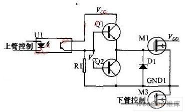
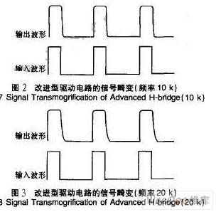
In the dual power optocoupler drive circuit scheme,use the output ofoptocoupler to direct-drive the MOS pipe, it would make the output waveform have a serious distortion,in particular the falling edge of the waveform is relatively slow, mainly caused by the capacitance between G and S of the MOS pipe. When the output waveform is high, charge to the capacitance between the G and S so that the wave increases slightly slow; when output waveform becomes low,the capacitance between G and S discharges through Rl to make the G of MOS pipe's potential decreasesvery slowly ,it leads to the the falling edge of the waveform has a serious distortion.
(View)
View full Circuit Diagram | Comments | Reading(794)
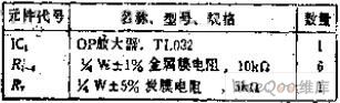
Magnification is 2 small vary the unbalanced output circuit
Published:2011/6/3 21:56:00 Author:Fiona | Keyword: Magnification is 2 , small vary the unbalanced output
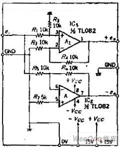
Circuit Work
Mention of the balanced output, people tend to immediately think of adding OP amplifier at the output of the positive-phase amplifier to be the inverting amplifier circuit, inverting the normal phase and the invert phase make up the balanced output. In the DC circuit, although this method can be used, but if it is broadband signal, phase shift of inverting amplifier is a problem. The drift of the OP amplifier A1 and A2 is equal in this circuit, so even if the input frequency changes,it won't happen phase distortion.
(View)
View full Circuit Diagram | Comments | Reading(385)
The wiper-washer circuit of Buick-Century
Published:2011/5/26 22:02:00 Author:Borg | Keyword: wiper-washer circuit, Buick-Century

Washer pump is controlled by a independent switch. The wiper has 4 gears of fog, off, low and high in total. When it is at the fog gear, the current comes from wiper fuse(25A), in the meantime, the relay in the P switch acquires the current and makes the terminals pull in, then the current goes into the motor, and the motor run for a course at a low speed, in which the course in interrupted. If therelay didn't pull in, the motor wouldn't work normally. In the Figure, there is no the electric delaying display circuit.
(View)
View full Circuit Diagram | Comments | Reading(529)
| Pages:402/471 At 20401402403404405406407408409410411412413414415416417418419420Under 20 |
Circuit Categories
power supply circuit
Amplifier Circuit
Basic Circuit
LED and Light Circuit
Sensor Circuit
Signal Processing
Electrical Equipment Circuit
Control Circuit
Remote Control Circuit
A/D-D/A Converter Circuit
Audio Circuit
Measuring and Test Circuit
Communication Circuit
Computer-Related Circuit
555 Circuit
Automotive Circuit
Repairing Circuit