
Index 407
SHARP SK-180 type display power supply circuit
Published:2011/6/5 3:22:00 Author:John | Keyword: display

SHARP SK-180 type display power supply circuit is shown below.
(View)
View full Circuit Diagram | Comments | Reading(819)
Metal proximity switch circuit diagram
Published:2011/5/29 2:19:00 Author:Lucas | Keyword: Metal proximity switch
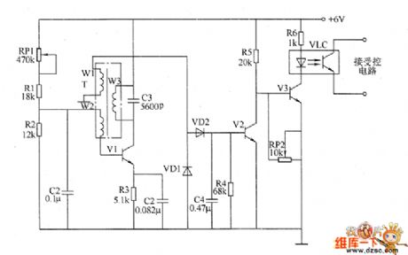
Metal proximity switch circuit consists of the high-frequency oscillator circuit, voltage rectifier circuit, and electronic switching circuit, the circuit is shown as the chart. High-frequency oscillator circuit consists of high-frequency transformer T, potentiometer RP1, resistors R1 ~ R3, capacitors C1 ~ C3 and transistor V1. Doubler rectifier circuit is composed of the diodes VD1 and VD2, capacitor C4 and resistor R4. Electronic switching circuit consists of transistors V2 and V3, potentiometer RP2, optocoupler VLC and resistors R5, R6. R1 ~ R6 use 1/4W metal film resistors or carbon film resistors. RP1 selects organic, solid potentiometer or variable resistor; RP2 uses synthetic carbon potentiometer or variable resistor. C1, C2 and C4 select monolithic capacitors; C3 uses high-frequency ceramic capacitor. VD1 and VD2 use IN4148 silicon switching diode. V1 and V2 use 59013 or 3DG6 silicon NPN transistor; V3 uses 58050 silicon NPN transistor. VLC uses 4N25 or 4N26 optocoupler.
(View)
View full Circuit Diagram | Comments | Reading(1696)
Electronic pressure switch circuit diagram
Published:2011/5/29 2:35:00 Author:Lucas | Keyword: Electronic pressure switch
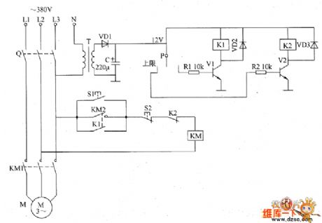
The electronic pressure switch circuit consists of the power circuit and pressure detection control circuit, the circuit is shown as the chart. Power circuit is composed of the power transformer T, rectifier diode VD1 and filter capacitor C. Pressure detection control circuit consists of the electric contact pressure gauge P, resistors R1 and R2, transistors V1 and V2, the relays K1 and K2, and diodes VD2, VD3. M is the air compressor motor, KM is the exchange of contact, Q is the knife switch, S1 is the start button, S2 is the stop button. The AC voltage between phase line L3 and zero line bucked by T, rectified by VD1 and filtered by C can provide 12V DC voltage for K1 and K2. R1 and R2 use 1/4W metal film resistors, or carbon film resistors. C uses aluminium electrolytic capacitor with voltage in 16V. VD1 ~ VD3 use 1N4007 silicon rectifier diodes. V1 and V2 use S8050, C8050 or 3DG8050 silicon NPN transistors.
(View)
View full Circuit Diagram | Comments | Reading(3407)
High voltage static generator circuit diagram 1
Published:2011/6/8 4:38:00 Author:Lucas | Keyword: High voltage , static generator

The high voltage static generator circuit is composed of the power switch S, power transformer T, rectifier diodes VD1 ~ VD9, capacitors C1 ~ C9, resistors R1 ~ R4, voltmeter PV and ammeter PA, and the circuit is shown as the chart. R1 ~ R4 select 1W high-voltage resistors. C1 ~ C9 select high voltage ceramic capacitors with the voltage in 30kV. VD1 ~ VD9 select silicon rectifier stack with the voltage in 30kV (it also can replaced by two silicon rectifier stacks connected in series with the voltage in 18 ~ 20KV)such as the model of 2CGL30, 2DGL30. PV chooses 0 ~ 100kV high-voltage voltmeter. PA selects 0 ~ 100A current meter. S uses 220V bipolar switch with the contact current capacity being greater than 5A.
(View)
View full Circuit Diagram | Comments | Reading(2395)
Metal detector circuit diagram 8
Published:2011/6/7 20:00:00 Author:Lucas | Keyword: Metal detector

The metal detector circuit is composed of the probe oscillator, PLL phase-locked loop circuit and the audio alarm circuit, and the circuit is shown as the chart. Probe oscillator is composed of the detection coil L, transistor VI, resistors RI ~ R3, capacitors C1 ~ C5. PLL phase-locked loop circuit consists of integrated circuit IC1, resistors R4 ~ R8, capacitors C7 ~ Cll. Audio alarm circuit is composed of the transistor V2, comparision amplifier integrated circuit IC2, buzzer HA, resistors R9 ~ R14. R1 ~ R14 use 1/4W carbon film resistors or metal film resistors; R15 uses 1/2W metal film resistor. RP uses small potentiometer or variable resistor. V1 and V2 use 59018 or 2SC1815 NPN silicon transistors.
(View)
View full Circuit Diagram | Comments | Reading(6459)
Metal detector circuit diagram 7
Published:2011/6/7 19:55:00 Author:Lucas | Keyword: Metal detector
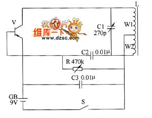
The metal detector uses LC single-tube oscillator circuit, and the circuit is shown as the chart. In the circuit, V is oscillating tube, L is the detection coil, C1 is the resonant capacitor. The LC single-tube oscillator circuit works after turning on the power switch S, the speaker of semiconductor superheterodyne radio will issue sounds with the frequency around 1kHz. When the detection coil L detects underground metal, the sound frequency of the speaker becomes high. R selects variable resistor. C1 uses variable capacitor (270P single sealed); C2 and C3 use high-frequency ceramic or glass glaze capacitors. V selects 3AG1 or 3AGll high frequency low power PNP germanium transistor. CB uses 9V tandem battery. Adjusting the resistance of R can make the operating current of machine be about 15mA.
(View)
View full Circuit Diagram | Comments | Reading(1048)
Metal detector circuit diagram 6
Published:2011/6/7 19:45:00 Author:Lucas | Keyword: Metal detector

The metal detector circuit is composed of the probe oscillator, reference oscillator, oscillation signal processor, mixing amplifier and ammeter PA and other components, and the circuit is shown as the chart. Probe oscillator is composed of the oscillating tube VI, explore coil L1, capacitors C1 ~ C4 and resistors R1 ~ R3 and so on. Reference oscillator is composed of the oscillating tube V2, inductor L2, capacitors C6 ~ C9 and resistors R2 ~ R4 and so on. Oscillation signal processor consists of six NOT gate (Dl ~ D6) integrated circuit IC and the external RC components. Hybrid amplifier is composed of the diode YD, resistors R12, R13, capacitors C13 and field-effect transistor VF. V1 and V2 use 59018 silicon NPN transistor. VF selects V20A field effect transistor.
(View)
View full Circuit Diagram | Comments | Reading(4864)
Metal detector circuit diagram 5
Published:2011/6/8 4:00:00 Author:Lucas | Keyword: Metal detector

The metal detector circuit consists of oscillator and sound-light alarm circuit, and the circuit is shown as the chart. Oscillator circuit consists of inductor L, capacitor C1, sensor switch integrated circuit IC1 (includes oscillator, detector and comparator circuit, etc.) and the peripheral components. Sound-light alarm circuit consists of four NOR gate integrated circuit IC2 (Dl ~ D4) and the light-emitting diode VL, speaker BL and other components. R1 ~ R6 select 1/4W carbon film resistors. C1 ~ C4 select ceramic capacitors. VL selects Φ5mm high-brightness light-emitting diode. V uses S9013 or C8050 silicon NPN transistor. IC1 uses TDA0161D sensor switch integrated circuit; IC2 selects CD4001 four NOR gate integrated circuit.
(View)
View full Circuit Diagram | Comments | Reading(2958)
Metal detector circuit diagram 4
Published:2011/6/7 19:39:00 Author:Lucas | Keyword: Metal detector
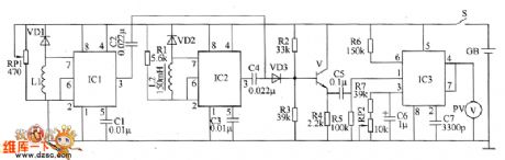
The metal detector circuit is composed of the probe oscillator, reference oscillator, mixer and signal display and other components, and the circuit is shown as the chart. Probe oscillator consists of time-based integrated circuit IC1, inductor L1, potentiometer RPI, diode VD1 and capacitors C1, C2. Reference oscillator (reference oscillator) circuit is composed of the time-base integrated circuit IC2, inductor L2, diode VD2, resistor RI and capacitors C3, C4. Mixer is composed of the transistor V, diode VD3 and resistors R2 ~ R4. Signal display circuit consists of integrated circuit IC3, voltage meter PV and peripheral capacitance resistance element. R1 ~ R7 choose 1/4W or 1/8W carbon film resistors. V uses 3DG6 or S9018 silicon NPN transistor.
(View)
View full Circuit Diagram | Comments | Reading(1337)
Metal detector circuit diagram 3
Published:2011/6/7 19:34:00 Author:Lucas | Keyword: metal detector

The metal detector is composed of the probe oscillator, reference oscillator and audio amplifier and other components, and the circuit is shown as the chart. Probe oscillator consists of transistors VI, V2 and detection coil L1, capacitor C1 and so on. Reference oscillator consists of transistors VI, Y3 and inductor L2, capacitor C3 and other components. Audio amplifier is composed of audio power amplifier IC IC, volume potentiometer RP and capacitors C6 ~ C8 RP and so on. R1 uses small or variable resistor; R2 ~ R5 select 1/4W metal film resistors. RP uses small membrane potentiometer. C1 uses high-frequency ceramic capacitor; C2, C5 ~ C8, CIO use aluminum electrolytic capacitor with the voltage in 10Y; C3 uses ceramic fine capacitor; C4, C9 select polyester or monolithic capacitors.
(View)
View full Circuit Diagram | Comments | Reading(4803)
Metal detector circuit diagram 2
Published:2011/6/8 4:09:00 Author:Lucas | Keyword: Metal detector

The metal detector circuit is composed of the power circuit, sine wave oscillator, PLL phase-locked loop circuit and hybrid amplifying circuit, and the circuit is shown as the chart. Power circuit is composed of the batteries GBI, GB2, filter capacitors C1, C2, and the power switch s (Sa, Sb). Sine oscillator circuit consists of transistor VI, detecting coil L, capacitors C3 ~ C5 and resistors RI, R2. PLL phase-locked loop circuit IC consists of dual time-base integrated circuit and resistos R3, potentiometer RP1, capacitors C6 ~ C8. Hybrid amplifying circuit is composed of the transistors V2, V3, resistors R4 ~ R6, potentiometer RP2 and ammeter PA. R1 ~ R6 use l/4W or l/8W carbon film resistors.
(View)
View full Circuit Diagram | Comments | Reading(4144)
TDA3654 field scanning output integrated circuit
Published:2011/6/8 19:02:00 Author:Christina | Keyword: field scanning, output, integrated circuit
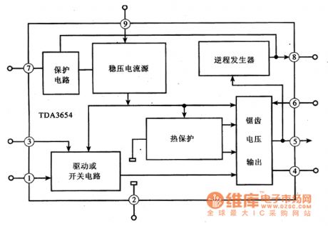
The TDA3654 is designed as one kind of field scanning output integrated circuit that is produced by the PHILIPS company, and it can be used in the domestic and imported color TVs.
1.Features
The maximum output current of the TDA3654 integrated circuit is 2.2Ap-p, the maximum output power is 15W. The internal circuit block diagram is as shown in figure 1. This IC can be directly used as the substitute of the TDA3653B and TDA3653C.
Figure 1 The internal circuit block diagram of the TDA3654 integrated circuit
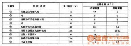
2.Pin functions and data
The TDA3654 integrated circuit is in the 9-pin single row package, the pin functions and data is as shown in the table 1.
Table 1 The pin functions and data of the TDA3654 integrated circuit
(View)
View full Circuit Diagram | Comments | Reading(1162)
TCO2/TCO3 type temperature sensor typical application circuit
Published:2011/6/8 21:29:00 Author:Christina | Keyword: temperature sensor, typical application
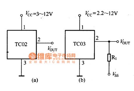
The TCO2/TCO3 type temperature sensor typical application circuit is as shown in the figure 26-11. When the TCO3 temperature sensor is used in the temperature measurement of lower than 0℃, you need to add the negative power supply Vss and the current limiting resistor R1 to the circuit, so the negative power supply's output current is 50μA, so R1=VSS/5OμA.
Figure:TCO2/TCO3 type temperature sensor typical application circuit (View)
View full Circuit Diagram | Comments | Reading(709)
TCO2/TCO3 type temperature sensor encapsulation mode circuit
Published:2011/6/8 21:30:00 Author:Christina | Keyword: temperature sensor, encapsulation mode

Figure:TCO2/TCO3 type temperature sensor encapsulation mode circuit (View)
View full Circuit Diagram | Comments | Reading(672)
TDA3504 G-Y chromatism matrix and base-color signal matrix integrated circuit
Published:2011/6/8 21:39:00 Author:Christina | Keyword: G-Y, chromatism matrix, base-color, signal, matrix, integrated circuit

The TDA3504 is designed as one kind of G-Y chromatism matrix and base-color signal matrix integrated circuit that is produced by the PHILIPS company, and it can be used in the domestic and imported large screen multi-standard color TVs.
1.Features
The TDA3504 has: the three-color matrix circuit, the 3-way signal switching circuit, the 3-way contrast control circuit, the 3-way brightness control circuit, the 3-way clamp circuit, the Y (brightness) signal amplification circuit, the brightness vanishing excitation circuitry, the selective passing and amplitude limit circuit.etc.
Figure 1 The internal circuit block diagram of the TDA3504 integrated circuit
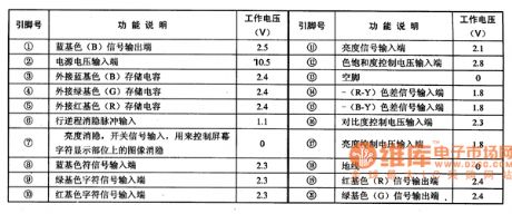
2.Pin functions and data
The TDA3504 integrated circuit is in the 20-pin double-row DIP package, the pin functions and data is as shown in table 1.
Table 1 The pin functions and data of the TDA3504 integrated circuit
(View)
View full Circuit Diagram | Comments | Reading(718)
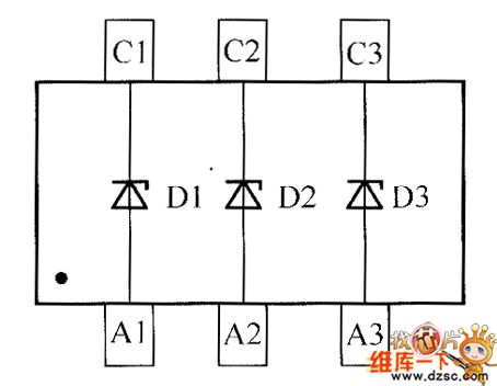
crystal diode DDZX9716TS internal circuit
Published:2011/6/6 9:54:00 Author:chopper | Keyword: crystal diode, internal
View full Circuit Diagram | Comments | Reading(341)
The inverter circuit diagram 1
Published:2011/6/3 2:16:00 Author:Lucas | Keyword: inverter
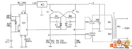
The inverter circuit consists of non-steady-state multivibrator, bistable flip-flop and switch output circuit, the circuit is shown as the chart. Astable multivibrator circuit is composed of time-base integrated circuit IC1, voltage regulator integrated circuit IC2 , resistors R1, R2, potentiometers RP, diode VD1 and capacitors C1, C2. Bistable trigger circuit consists of transistors V1, V2, resistors R3 ~ R6, capacitors C3, C4 and diodes VD2, VD3. Switch output circuit consists of thyristors VT1, VT2 and transformer T. After the power switch S is turned on, one road of the +12 V voltage of battery GB can directly povide power supply for bistable trigger, the other road is stabilized as +6 V for the astable multivibrator circuit.
(View)
View full Circuit Diagram | Comments | Reading(1254)
The interface circuit diagram between MSP430F413 and MFRC522
Published:2011/6/3 2:15:00 Author:Lucas | Keyword: interface
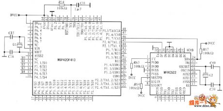
It sets theMSP430F413 as the example, and it uses I2C interfaces. The circuit is shown in Fig. Because the SCM MSP430F413 has no the port line with interface function being similar to I2C,it usesI / 0 simulation I2C timing sequence.
(View)
View full Circuit Diagram | Comments | Reading(3438)
555 calculator/stopwatch convertor circuit
Published:2011/6/7 2:11:00 Author:TaoXi | Keyword: 555, calculator, stopwatch, convertor
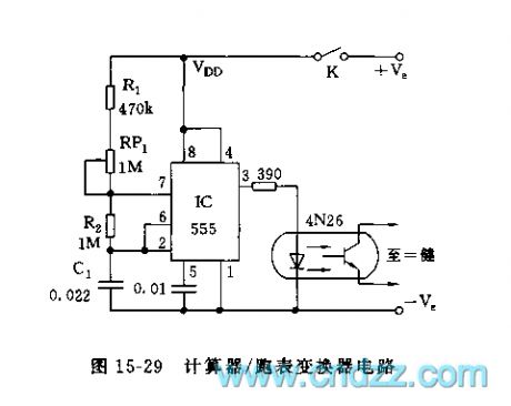
As the figure 15-29 shows, the convertor is composed of the time-base pulse generator and the photoelectric isolating device. The astable multivibrator is composed of the 555 and the R1, R2, RP1, C1, the oscillation frequency f=1.44/(R1+RP1+2R2)C1, by adjusting RP1, you can make the frequency to 60Hz. The output of pin-3 adds to the photoelectric coupler through the current limiting resistor, and the output also adds to any calculator buttons which have the automatic constant, so it can be used as the stopwatch.
(View)
View full Circuit Diagram | Comments | Reading(1374)
monolithic temperature sensor circuit
Published:2011/5/29 8:13:00 Author:chopper | Keyword: monolithic, temperature sensor
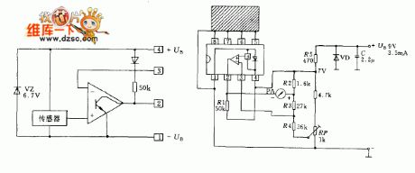
Integrated circuit LM3911 is a silicon sensor composed of operational amplifier and voltage regulator circuit.It can be a simple electrical thermometer only by using a few external components.Transistor is used as a temperature-sensing element on the silicon chip.The voltage of base and emitter of the transistor varies with temperature changes.When the temperature rises,the voltage will increase.Outside temperature intussuscepted from a copper billet will be passed on to the temperature sensor.The copper billet will be connected to pins 5~8 of the integrated circuit and the inside parts of these pins are connected to temperature sensor.
(View)
View full Circuit Diagram | Comments | Reading(598)
| Pages:407/471 At 20401402403404405406407408409410411412413414415416417418419420Under 20 |
Circuit Categories
power supply circuit
Amplifier Circuit
Basic Circuit
LED and Light Circuit
Sensor Circuit
Signal Processing
Electrical Equipment Circuit
Control Circuit
Remote Control Circuit
A/D-D/A Converter Circuit
Audio Circuit
Measuring and Test Circuit
Communication Circuit
Computer-Related Circuit
555 Circuit
Automotive Circuit
Repairing Circuit