Basic Circuit
Metal detector circuit diagram 7
Published:2011/6/7 19:55:00 Author:Lucas | Keyword: Metal detector | From:SeekIC

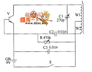
The metal detector uses LC single-tube oscillator circuit, and the circuit is shown as the chart. In the circuit, V is oscillating tube, L is the detection coil, C1 is the resonant capacitor. The LC single-tube oscillator circuit works after turning on the power switch S, the speaker of semiconductor superheterodyne radio will issue sounds with the frequency around 1kHz. When the detection coil L detects underground metal, the sound frequency of the speaker becomes high. R selects variable resistor. C1 uses variable capacitor (270P single sealed); C2 and C3 use high-frequency ceramic or glass glaze capacitors. V selects 3AG1 or 3AGll high frequency low power PNP germanium transistor. CB uses 9V tandem battery. Adjusting the resistance of R can make the operating current of machine be about 15mA.
Reprinted Url Of This Article:
http://www.seekic.com/circuit_diagram/Basic_Circuit/Metal_detector_circuit_diagram_7.html
Print this Page | Comments | Reading(3)

Article Categories
power supply circuit
Amplifier Circuit
Basic Circuit
LED and Light Circuit
Sensor Circuit
Signal Processing
Electrical Equipment Circuit
Control Circuit
Remote Control Circuit
A/D-D/A Converter Circuit
Audio Circuit
Measuring and Test Circuit
Communication Circuit
Computer-Related Circuit
555 Circuit
Automotive Circuit
Repairing Circuit
Code: