Basic Circuit
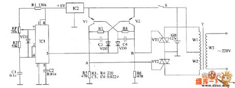
The inverter circuit diagram 1
Published:2011/6/3 2:16:00 Author:Lucas | Keyword: inverter | From:SeekIC

The inverter circuit consists of non-steady-state multivibrator, bistable flip-flop and switch output circuit, the circuit is shown as the chart. Astable multivibrator circuit is composed of time-base integrated circuit IC1, voltage regulator integrated circuit IC2 , resistors R1, R2, potentiometers RP, diode VD1 and capacitors C1, C2. Bistable trigger circuit consists of transistors V1, V2, resistors R3 ~ R6, capacitors C3, C4 and diodes VD2, VD3. Switch output circuit consists of thyristors VT1, VT2 and transformer T. After the power switch S is turned on, one road of the +12 V voltage of battery GB can directly povide power supply for bistable trigger, the other road is stabilized as +6 V for the astable multivibrator circuit.
Reprinted Url Of This Article:
http://www.seekic.com/circuit_diagram/Basic_Circuit/The_inverter_circuit_diagram_1.html
Print this Page | Comments | Reading(3)

Article Categories
power supply circuit
Amplifier Circuit
Basic Circuit
LED and Light Circuit
Sensor Circuit
Signal Processing
Electrical Equipment Circuit
Control Circuit
Remote Control Circuit
A/D-D/A Converter Circuit
Audio Circuit
Measuring and Test Circuit
Communication Circuit
Computer-Related Circuit
555 Circuit
Automotive Circuit
Repairing Circuit
Code: