
Index 412
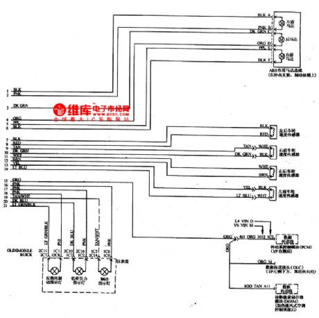
The ground connections of Buick-Century (see Figure 1,2,3)
Published:2011/5/18 3:22:00 Author:Borg | Keyword: ground connections, Buick-Century
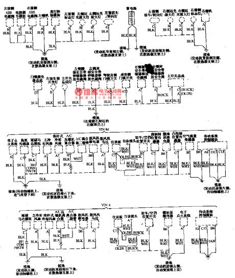
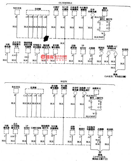
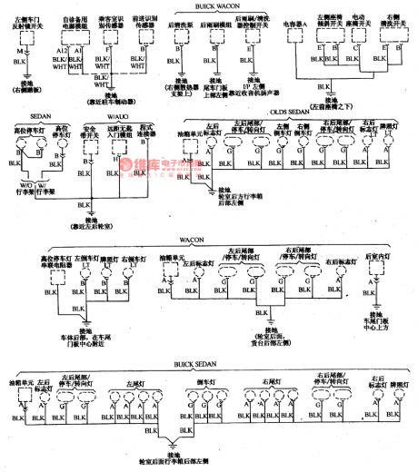
These years, it is the common point of importing car circuits to explicitly describe the ground connections of electric equipment, as the car electric equipment is fixed throughout the car, and many general parts are fixed on metal slides and shaking engines or brackets, so its not dependable to connect in a single line. It is necessary to link all the ground connections into a reliable net with the negative point of the battery, which is also convenient to detect partial faults. The following shows the chief ground connections:
The ground connections of Buick-Century (1)
(View)
View full Circuit Diagram | Comments | Reading(853)
The electric control circuit if Buick-Century engine and auto transmission(2)
Published:2011/5/18 20:01:00 Author:Borg | Keyword: control circuit, Buick-Century

The control system PCM(a) of Buick-Century engine(3.1L)The notes of terminal No. And wire colors are clear, and the wires are also marked with No., which is convenient to check, for example, the No. of fault indicator wire is 419, brown/white stripe, which is linked to the No.1 terminal of connector C. The colors of other wires are as follows. BLK一black LTGRN一light green DKGRN一dark green TAN一tan BLU一blue ORG一orange GRN一green VlO一violet BRN一brown PNK一pink GRY一grey WHT一white CLR一clear (View)
View full Circuit Diagram | Comments | Reading(1359)
Toshiba CV60 elevator safety loop circuit
Published:2011/5/19 8:51:00 Author:TaoXi | Keyword: Toshiba, elevator, safety loop
Toshiba CV60 elevator safety loop circuit (View)
View full Circuit Diagram | Comments | Reading(948)
Active half-frequency circuit
Published:2011/5/19 19:53:00 Author:Christina | Keyword: Active, half-frequency
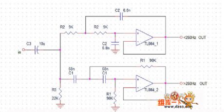
The crossover point of the active half-frequency circuit is 260Hz, the figure shows only one sound channel, the other sound channel is the same, the op-amp IC can select a 4-channel op-amp TL084 (voltage: 7V-36V), or the op-amp IC can select two NE5532 (10-30V), JRC4850(4-32V).
(View)
View full Circuit Diagram | Comments | Reading(1409)
Toshiba CV60 elevator DC door opening circuit
Published:2011/5/19 8:52:00 Author:TaoXi | Keyword: Toshiba, elevator, DC, door opening
Toshiba CV60 elevator DC door opening circuit (View)
View full Circuit Diagram | Comments | Reading(508)
Toshiba CVl80 elevator safety loop circuit
Published:2011/5/19 8:44:00 Author:TaoXi | Keyword: Toshiba, elevator, safety loop
Toshiba CVl80 elevator safety loop circuit (View)
View full Circuit Diagram | Comments | Reading(420)
Toshiba CV60 (7.5 kW) elevator main circuit
Published:2011/5/19 8:54:00 Author:TaoXi | Keyword: Toshiba, elevator, main circuit
Toshiba CV60 (7.5 kW) elevator main circuit (View)
View full Circuit Diagram | Comments | Reading(526)
Toshiba CV180 elevator main circuit
Published:2011/5/19 8:56:00 Author:TaoXi | Keyword: Toshiba, elevator, main circuit
Toshiba CV180 elevator main circuit (View)
View full Circuit Diagram | Comments | Reading(543)
The ABS circuit of Buick-Century
Published:2011/5/18 2:48:00 Author:Borg | Keyword: ABS, Buick-Century

The ABS is used to control the range of slip rate between wheels and the ground when braking the car, which can prevent the wheel locking and slipping, so that the steering control and side-slipping can be avoided. When the sensor delivers the differentia between wheels and the car indicating the wheel is locked, the ABS computer will give order to activate the magnetic valve to reduce the pressure of the brake cylinder. The circuit is shown in Figure 1 and Figure 2.
Figure 1. The ABS system of Buick-Century
(View)
View full Circuit Diagram | Comments | Reading(838)
Pyroelectric infrared sensing socket analog sound circuit BISS0001
Published:2011/5/11 19:03:00 Author:TaoXi | Keyword: Pyroelectric, infrared sensing socket, analog sound
The circuit is as shown. It is composed of the pyroelectric infrared sensor, the infrared signal processing circuit, the relay control socket circuit, the analog sound circuit and the AC step-down rectifier circuit.etc. When someone walked into the pyroelectric infrared monitoring field, the socket gets the electricity, its electrical equipments start running; meanwhile, the analog sound circuit sends out the voice to remind the equipment master. (View)
View full Circuit Diagram | Comments | Reading(569)
The instrument, indicator and warning lamp circuit of Buick-Century
Published:2011/5/18 2:16:00 Author:Borg | Keyword: instrument, indicator, warning lamp, Buick-Century
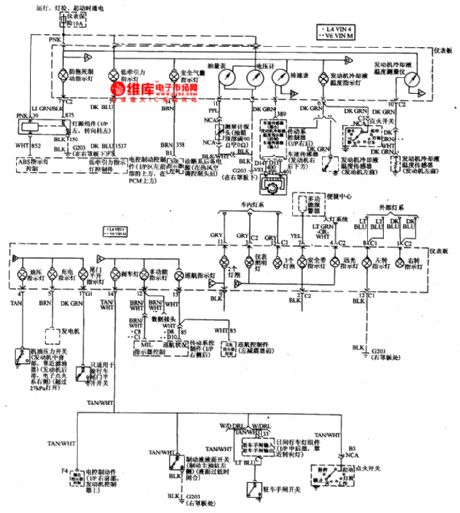
The instrument, indicator and warning lamp circuit of Buick-Century is like that of other cars, the instruments include coolant thermometer, fuel gauge, engine rotating speed meter, speedometer, and it is also fixed with a voltmeter.
There are many warning lamps, such as the oil pressure warning lamp, charging indicator, brake indicator, high beam indicator, left-steering indicator, right-steering indicator, seatbelt indicator, cruise indicator, tail gate indicator, air bag indicator, low drive indicator and anti brake lock indicator, etc. (View)
View full Circuit Diagram | Comments | Reading(813)
Plastic bag sealing machine circuit diagram 2
Published:2011/5/18 19:50:00 Author:Lucas | Keyword: Plastic bag , sealing machine
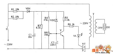
The plastic bag sealing circuit is composed of power supply circuit and heating control circuit, the circuit is shown as the chart. Power supply circuit is composed of the power button S, resistors R1, R2, rectifier diode VD1 and filter capacitor C1. Heating control circuit consists of transistor V, thyristor VT, resistors R4 ~ R6, potentiometer RP, power transformer T, light-emitting diode VL and strip heater EH. power button S is controlled by the heating operating handle. When people use it, the plastic bag should be pressed on the strip heater EH, and after pressing the operating handle, the AC 220V voltage is limited and bucked by R1, rectified by VD1 and filtered by C1, then it provides DC operating power for V by R4, RP and R5.
(View)
View full Circuit Diagram | Comments | Reading(5826)
Magnetic stirring apparatus circuit diagram 1
Published:2011/5/18 0:28:00 Author:Lucas | Keyword: Magnetic stirring apparatus
The magnetic stirring apparatus circuit is composed of the power circuit, heating control circuit, clock oscillator, pulse distribution controller and the solenoid controller, the circuit is shown as the chart. Power circuit is composed of the power switch S1, the power transformer T, rectifier bridge pile UR, three-terminal voltage regulator integrated circuit IC6 and filter capacitor C3, C4.Heating control circuit consists of resistors R12 ~ R15, potentiometer RP2, heating control switch S2, capacitor C2, NAND integrated circuit IC1 (D1 ~ D4) and the onternal D3, D4, transistor V4, diode VD4, and relay K, electric heater EH. (View)
View full Circuit Diagram | Comments | Reading(2376)
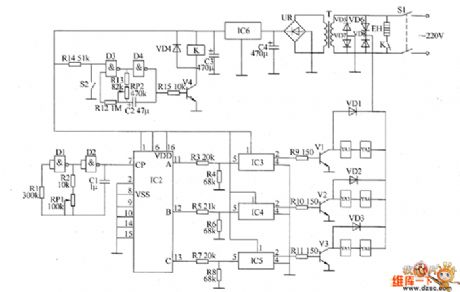
Magnetic stirring apparatus circuit diagram 2
Published:2011/5/18 6:03:00 Author:Lucas | Keyword: Magnetic stirring apparatus

The magnetic stirring apparatus circuit is composed of the power circuit, mixing motor control circuit, heating thermostat circuit, mixing motor speed control circuit, timing alarm circuit and timing control circuit, the circuit is shown as the chart. The power circuit is composed of the power switch S1, the power transformer T, rectifier bridge pile UR1, resistor R1, power indicator HL1 and filter capacitor C2. Heating thermostat circuit is composed of heating switch circuit S3 (S3-l, S3-2), electric contact thermometer Q2, resistors R4 ~ R7, capacitors C1 and C3, the transistor V2 ~ V5, electric heater EH, temperature indicator HL3, heating lamp HL4, diode VD2, relay K3, potentiometers RP2 and RP3, thyristor VT and rectifier bridge UR2 and UR3. (View)
View full Circuit Diagram | Comments | Reading(1235)
The brief introduction of the Buick car produced by Shanghai GM Corp.
Published:2011/5/18 Author:Borg | Keyword: brief introduction, Buick, Shanghai
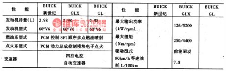
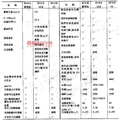
Shanghai GM Corp. Ltd is the largest Sino-US joint venture, which is joint-ventured by Shanghai Automotive Industry Corporation(Group) and GM,the USA, by far, 1.52 billion dollars have been invented in it. And the Buick cars produced by it will reach the high standard of the world, the main feature parameters are listed in Table 6-2.1.the engine and auto transmission3.0 L 60°V6 4-course petrol engine, high efficiency, low noise, good momentum,oil injection and electric igniting system with fuel-saving FI sequence multiple terminals, slight pollution.PCM momentum general computer control module will control and adjust automatically control the system according to the engine load, road condition, altitude and atmosphere, by which the engine can keep high efficiency and low oil consumption. 4-gear electrically controlled transmission can regulate the transmitting time, keep the best functions and smooth transmission in accordance with different conditions.
(View)
View full Circuit Diagram | Comments | Reading(525)
Plastic bag sealing machine circuit diagram 1
Published:2011/5/18 19:38:00 Author:Lucas | Keyword: Plastic bag , sealing machine

The plastic sealing circuit is composed of power circuit, control circuit and heating circuit, the circuit is shown as the chart. Power supply circuit is composed of rectifier diode VD1, filter capacitor C1 and the step-down resistors R1, R2. Control circuit is composed of control button S, resistors R3, R4, potentiometer RP, capacitor C2, diode VD2, transistor V, voltage regulator diode VS, thyristor VT, light-emitting diode VL and relay K. Heating circuit is composed of normally open contact K and power transformer T, heater EH. Adjusting the resistance of RP can change the charging time of C2, thus change the EH heating time to adapt the sealing with different thickness and material.
(View)
View full Circuit Diagram | Comments | Reading(13702)
The fault codes of 8A-FE engine control system
Published:2011/5/13 9:26:00 Author:Borg | Keyword: fault codes, control system
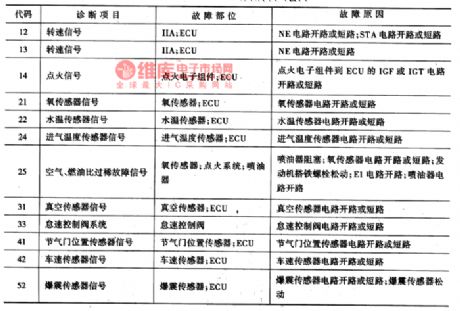
The fault codes of 8A-FE engine control system are listed in Table2.
Table 2. the codes of 8A-FE engine control system
(View)
View full Circuit Diagram | Comments | Reading(549)
Improving sound quality of F15 power amplifier circuit diagram
Published:2011/5/17 21:21:00 Author:Ecco | Keyword: Improving , sound quality , power amplifier
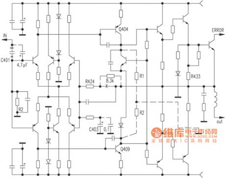
According to the figure, this is a fully symmetrical, full complement, double differential circuit. Firstly, the C401 10μF ordinary electrolytic input capacitor should be replaced by a 4.7μF CBB capacitor; then both ends of the feedback blocking capacitor C403 are added the WIMA 0.1μF capacitor, this would obviously make the sound be more smooth and clear; the second step, for improving the open-loop instructions, motivation level Q404, Q409 should be added 10kΩ collector load resistors R1, R2, while the feedback resistor R424 is connected a 8.3kΩ resistor in series, this can give a more natural sound with better transient, while the gain does not decrease and increase slightly.
(View)
View full Circuit Diagram | Comments | Reading(679)
The electric rear-view mirror circuit of Buick-Century
Published:2011/5/17 22:26:00 Author:Borg | Keyword: rear-view mirror, Buick-Century
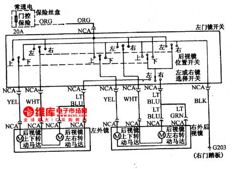
As the electric mirror circuits of other cars, the vertical adjustment of Buick-Century is done by the up/down switches, the horizon adjustment is done by the right/left switches, and the left or right mirror is set with a selective switch.
(View)
View full Circuit Diagram | Comments | Reading(649)
The engine control circuit of Buick-Century 3.3L(4)
Published:2011/5/17 20:19:00 Author:Borg | Keyword: engine control circuit, Buick-Century
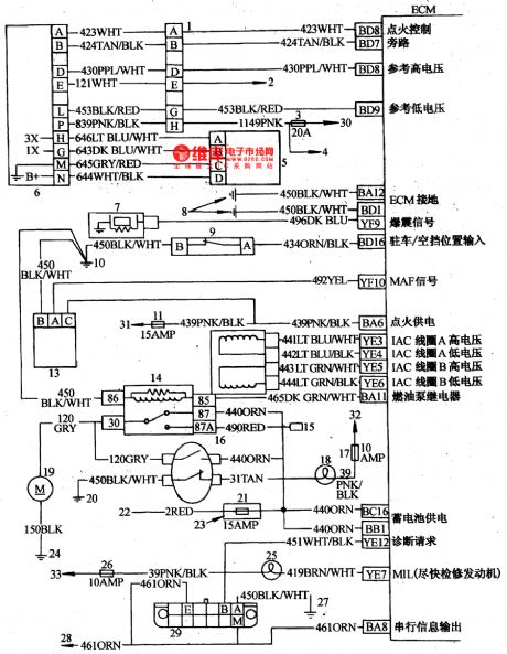
The engine control circuit of Buick-Century 3.3L1-igniting switch wire 8-lead pin connector; 2-tachometer on the instrument(if there is); 3-oil injector coil fuse; 4-oil injector; 5-crank position sensor; 6-igniting control module; 7-explosive sensor; 8,10,20,7-transmission ground connection; 9-p/n switch; 11-ECM fuse; 12-idling speed control motor; 13-air flow meter; 14-fuel pump relay; 15-oil pump test connector; 16-engine oil pressure switch.
(View)
View full Circuit Diagram | Comments | Reading(1021)
| Pages:412/471 At 20401402403404405406407408409410411412413414415416417418419420Under 20 |
Circuit Categories
power supply circuit
Amplifier Circuit
Basic Circuit
LED and Light Circuit
Sensor Circuit
Signal Processing
Electrical Equipment Circuit
Control Circuit
Remote Control Circuit
A/D-D/A Converter Circuit
Audio Circuit
Measuring and Test Circuit
Communication Circuit
Computer-Related Circuit
555 Circuit
Automotive Circuit
Repairing Circuit