
Index 400
Agricultural automatical water feeder circuit diagarm 15
Published:2011/6/14 5:49:00 Author:Lucas | Keyword: Agricultural, automatical water feeder

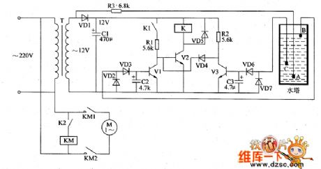
The agricultural automatical water feeder circuit is composed of the water level detection control circuit, sound and light alarm circuit and power supply circuit,and the circuit is shown as the chart 1. Power supply circuit is composed of the power switch s, power transformer T, rectifier diodes VD1 ~ VD4, fuse FU, filter capacitor C and the three-terminal voltage regulator integrated circuit IC. Water level detection control circuit consists of water level detection electrodes A ~ H, transistors V1 ~ V6, relays K1 ~ K3, diodes VD5 ~ VD7 and resistors R1 ~ R3. Sound and light alarm circuit is composed of the lights HL1, HL2, HA, and alarm control contacts K1 ~ K3. R1 ~ R3 select 1/4W carbon film resistors or metal film resistors.
(View)
View full Circuit Diagram | Comments | Reading(457)
Agricultural automatical water feeder circuit diagarm 14
Published:2011/6/14 6:09:00 Author:Lucas | Keyword: Agricultural , automatical water feeder
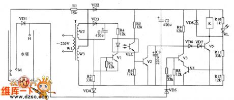
The agricultural automatical water feeder circuit is composed of the power supply circuit, water level detection circuit, control circuit and control implementation circuit, and the circuit is shown as the chart 1. Power supply circuit is composed of the power transformer T, rectifier diodes VD2, VD3, and filter capacitors C1, C2. Water level detection circuit is composed of water level detecting electrode H, electrode L, electrode M, diode VD1 and resistor R1. Control circuit consists of transistors V1 ~ V4, resistosr R2 ~ R9, R11, R12, diodes VD4, VD5, optical coupler VLC and capacitor C3. Control implementation circuit consists of the transistor V5, diodes VD6 ~ VD8 and relay K.
(View)
View full Circuit Diagram | Comments | Reading(432)
Agricultural automatical water feeder circuit diagarm 13
Published:2011/6/14 5:45:00 Author:Lucas | Keyword: Agricultural , automatical water feeder
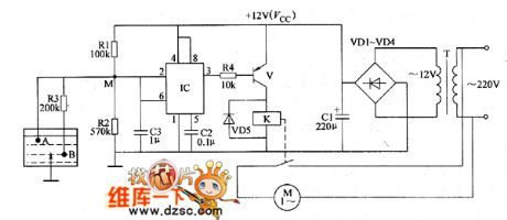
The agricultural automatical water feeder circuit is composed of the electrode A, electrode B, time-base integrated circuit IC, control transistor V, power transformer T, rectifier diodes VD1 ~ VD4 and relay K and other components, and the circuit is shown as the chart 1. AC 220V voltage is bucked by T, rectified by VD1 ~ VD4 and filtered by capacitor C1 to provide DC 12V voltage (Vcc) for IC as the operating voltage. R1 ~ R4 select l/4W or 1/8W carbon film resistors. Cl chooses the aluminum electrolytic capacitor with the voltage in 16V; C2 and C3 select monolithic capacitors. VD1 ~ VD5 use 1N4007 type silicon rectifier diodes. V uses C8050 silicon PNP transistor. K selects JRX-13F 12V DC relay.
(View)
View full Circuit Diagram | Comments | Reading(429)
Agricultural automatical water feeder circuit diagarm 11
Published:2011/6/14 6:25:00 Author:Lucas | Keyword: Agricultural , automatical water feeder
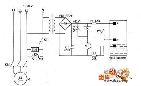
The agricultural automatical water feeder circuit is composed of the power supply circuit, water level detection circuit and control implementation circuit, and the circuit is shown as the chart 1. Power supply circuit is composed of the power transformer T, rectifier diodes VD1 ~ VD4 and filter capacitor C. Water level detection circuit is composed of the high water level electrode A, low water level electrode B and the main electrode C. Control implementation circuit is composed of the relay K, control transistor V and AC contactor KM and other components. AC 220Y voltage is bucked by T, rectified by VD1 ~ VD4 and filtered by C to produce the DC 12V voltage for control implementation circuit.
(View)
View full Circuit Diagram | Comments | Reading(429)
Agricultural automatical water feeder circuit diagarm 10
Published:2011/6/14 6:21:00 Author:Lucas | Keyword: Agricultural , automatical water feeder
The agricultural automatical water feeder circuit is composed of power supply circuit, water level detection circuit and pump control circuit, and the circuit is shown as the chart 1. The power supply circuit is composed of the power transformer T, rectifier diode VD1 and filter capacitor C1 and other components. Water level detection circuit is composed of the main electrode A, high water level electrode B, low water level electrode C and control tubes V1, V3 and so on. Pump control circuit consists of the relay K, relay drive tube V2, AC contactor KM and so on. R1 ~ R3 select 1/4W carbon film resistors. C1 ~ C3 select the aluminum electrolytic capacitors with the voltage in 16V. VD1 ~ VD7 use 1 N4007 silicon rectifier diodes.
(View)
View full Circuit Diagram | Comments | Reading(959)
Agricultural automatical water feeder circuit diagarm 19
Published:2011/6/14 6:15:00 Author:Lucas | Keyword: Agricultural, automatical water feeder
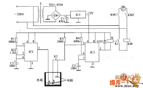
The agricultural automatical water feeder circuit is composed of the power supply circuit, multivibrator, monostable trigger, relay K, AC contactor KM and water detection electrodes (a ~ c) and other components, and the circuit is shown as the chart 1. Power supply circuit is composed of the power transformer T, rectifier diodes VD1 ~ VD4, three-terminal integrated voltage regulator IC1 and filter capacitor C1. Multivibrator is composed of the time-base integrated circuit IC2, resistors R1, R2 and capacitor C2 and so on. The monostable trigger is composed of the time-base integrated circuit IC3, resistors R3, R4, and capacitor C3 and other components. R1 ~ R4 select 1/4W carbon film resistors.
(View)
View full Circuit Diagram | Comments | Reading(436)
Agricultural automatical water feeder circuit diagarm 8
Published:2011/6/14 6:04:00 Author:Lucas | Keyword: Agricultural , automatical water feeder
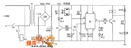
The agricultural automatical water feeder circuit is composed of the power supply circuit, detection circuit, monostable trigger circuit, control circuit and the water full alarm circuit and other components, and the circuit is shown as the chart 1. Power supply circuit is composed of the power switch S1, power transformer T, rectifier diodes VD1 ~ VD4 and filter capacitor C1. Water level detection circuit is composed of the water level detecting sensor (electrode) and variable resistor Ⅲ and so on. Monostable trigger circuit consists of time-base integrated circuit IC and external related components. Control circuit is composed of the relay K, driver transistor V2 and other components.
(View)
View full Circuit Diagram | Comments | Reading(416)
Agricultural automatical water feeder circuit diagarm 7
Published:2011/6/16 6:02:00 Author:Lucas | Keyword: Agricultural , automatical, water feeder
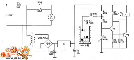
The agricultural automatical water feeder circuit is composed of the power supply circuit, water level detection circuit and control circuit, and the circuit is shown as the Figure 1. Power supply circuit is composed of the power transformer T, rectifier diodes VD1 ~ VD4, filter capacitors C1, C2 and integrated three-terminal regulator IC. Detection circuit consists of the upper electrode H, lower electrode L, variable resistor R2 and transistors V1 and so on. Control circuit consists of transistor V2, relay K1 and other components. R1, R3 and R5 ~ R7 select 1/4W carbon film resistors; R2 uses small full-sealed variable resistor.
(View)
View full Circuit Diagram | Comments | Reading(559)
Agricultural automatical water feeder circuit diagarm 6
Published:2011/6/16 5:58:00 Author:Lucas | Keyword: Agricultural, automatical, water feeder

The agricultural automatical water feeder circuit is composed of the power supply circuit, water level detection circuit , control implementation circuit, and the circuit is shown as the Figure 1. Power supply circuit is composed of the knife switch Q, fuse FU, power transformer T, rectifier diodes VD1 ~ VD4, filter capacitor C1, resistor R1 and limiting regulator diode VS. Water level detection circuit consists of the high water level electrode H, low water level electrode L and the main electrode M. Control implementation circuit is composed of the transistor V, Relay K, time-base integrated circuit IC, diodes VD5 ~ VD8 and external RC components.
(View)
View full Circuit Diagram | Comments | Reading(538)
Agricultural automatical water feeder circuit diagarm 4
Published:2011/6/16 5:54:00 Author:Lucas | Keyword: Agricultural , automatical, water feeder
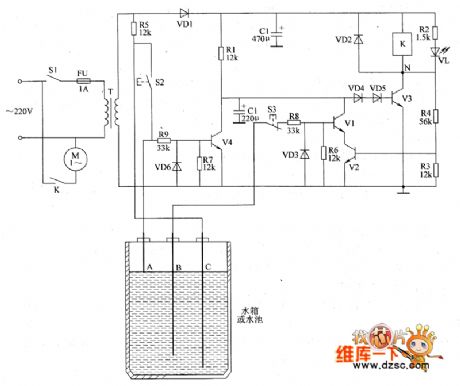
The agricultural automatical water feeder circuit is composed of the power supply circuit, water level detection control circuit and control implementation circuit, and the circuit is shown as the Figure 1. Power supply circuit is composed of the power switch S1, fuse FU, power transformer T, rectifier diode VD1 and filter capacitor Ct. Water level detection control circuit is composed of the water level detection electrodes A ~ C, resistors R1, R5 ~ R9, diodes VD3, VD6 transistor V4, capacitor C2 and control buttons S2, S3. Control implementation circuit is composed of the diodes VD2, VD4, VD5, resistors R2 ~ Rz +, transistors V1 ~ V3, light-emitting diode VL and relay K.
(View)
View full Circuit Diagram | Comments | Reading(573)
Agricultural automatical water feeder circuit diagarm 3
Published:2011/6/16 5:51:00 Author:Lucas | Keyword: Agricultural , automatical , water feeder
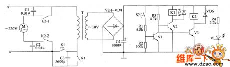
The agricultural automatical water feeder circuit is composed of the power supply circuit and control circuit, and the circuit is shown as the Figure 1. Power supply circuit is composed of the power control button S1, the normally open contacts of relay K1, power transformer T, rectifier diodes VD1 ~ VD4, capacitors C3, C4, resistor M and power indicator LED VL. The control circuit is composed of the triggered button S2, resistors R1 ~ R3, transistors V1 ~ V3, diodes VD5, VD6, capacitors C1, C2 and relays K1, K2. RI ~ R4 select l/4W metal film resistors or carbon film resistors.
(View)
View full Circuit Diagram | Comments | Reading(546)
White LED drive circuit composed of TL499A
Published:2011/6/13 6:16:00 Author:Lucas | Keyword: White LED, drive circuit
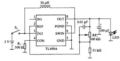
Figure 2-12 shows the white LED drive circuit which is composed of the TM499A. The white LED driver voltage is about 3.6 V. If it uses an ordinary battery to supply power, you need the step-up circuit, and it uses the boost circuit composed of the TL499A. TL499A is an integrated regulator with adjustable output voltage, and when it boosts, it needs switching regulator mode, and when it bucks, it needs the linear regulator mode. The two working modes can change automatically according to the input voltage. Input voltage range is 1.1 10V (switching work), and the maximum voltage is 35V (linear regulator work); the output voltage range is 2.9 to 30V, the maximum output current is 100mA. In the figure, the working power supply is supplied by 1- 2 batteries which are connected in series, and Ip is the controlling peak switch current of pin 4 in TL499A, and when Rl is 5OOΩ, Ip is about 2OOmA.
(View)
View full Circuit Diagram | Comments | Reading(2119)
MC3425 over power monitoring circuit, voltage regulator
Published:2011/6/14 4:42:00 Author:Lucas | Keyword: over power , monitoring circuit, voltage regulator
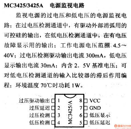
MC3425 over power monitoring circuit, voltage regulator, DC-DC circuit, pin and features of PWU
It is the power monitoring circuit with over-voltage and low voltage; in over-voltage detection channel, there is the external SCR output which is used to drive external arc extinction; in the low-voltage detection channel, there is a display with the output voltage failure; the work voltage range is 4.4 ~ 40V; the over-voltage detection driver output current is 300mA, and low voltage display output current is 30mA;the inter includes 2.5V reference voltage, which can do the programming on the hysteresis of input comparator in the low voltage detection channel, and when the temperature is at 70 ℃, the power consumption is 1w.
(View)
View full Circuit Diagram | Comments | Reading(454)
555 multi-function analog audio circuit
Published:2011/6/15 6:45:00 Author:TaoXi | Keyword: 555, multi-function, analog, audio
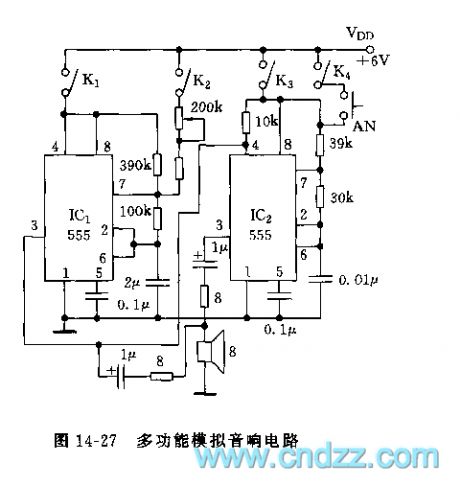
As the figure 14-27 shows, the multivibrator which is composed of two bipolar type 555s (or a 556) and the capacitance resistance elements can form a variety kinds of analog audio circuits. The oscillation frequency of IC1 is about 1Hz, the duty ratio is about 80%. The oscillation frequency of IC2 is about 1500Hz. By using the opening and closing of the switch, this circuit can simulate different sounds. For example, when you just turn on the K1, the IC1 starts working, the circuit will send out the monotonous second signal; if you just turn on the K4, the IC2 starts working, the circuit will send out the 1500Hz alarm signal; if you turn on the K3 and K4 at the same time, you can realize the modulation of IC1 to IC2, the circuit will send out the intermittently sound.
(View)
View full Circuit Diagram | Comments | Reading(667)
555 autoplay radio gymnastics record device circuit
Published:2011/6/14 3:52:00 Author:TaoXi | Keyword: 555, autoplay, radio gymnastics, record device
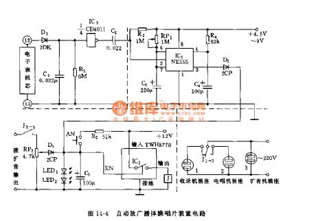
As the figure 14-4 shows, this device is composed of the electronic watch timer, the monostable circuit, the delay amplitude discriminator circuit.etc. And this device can be used to timing play the radio gymnastics record every day.
The timing signal is from the pin-12 and pin-13 of the electronic watch, when the electronic watch jumps from the 11:P to 12:A, the IC3(1/4CD4011) outputs a negative pulse transition to trigger the monostable timing circuit which composed of the 555 and RP1, C3, the timing time td=1.1RP1C3, the figure parameters' maximum delay is about 8 minutes.
The amplitude discriminator which is composed of the C5, TWH8778, LED1, LED2, J has the delay function, J1-2(left) is the contact-point of the normally closed relay, when the radio socket has the electricity, the radio starts working.
Figure 14-4 The 555 autoplay radio gymnastics record device circuit (View)
View full Circuit Diagram | Comments | Reading(788)
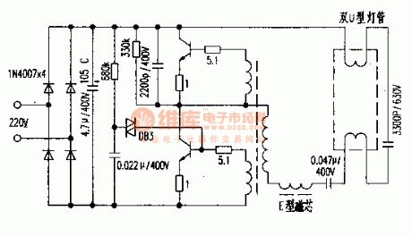
The electric ballast circuit of 3300P/630V
Published:2011/6/15 2:35:00 Author:Borg | Keyword: electric ballast
View full Circuit Diagram | Comments | Reading(606)
Typical Application Circuit of M54123 Intergrated Circuit
Published:2011/5/16 20:54:00 Author:Michel | Keyword: Application Circuit , Intergrated Circuit

Typical Application Circuit
Typical application circuitof leakage protecter composed of M54123 IC is showed as above.
Picture:Typical Application Circuit of M54123 Intergrated Circuit
Note:China's homegrown part number of M54123 IC is SF4123 and they can be used interchangeably directly.
(View)
View full Circuit Diagram | Comments | Reading(1446)
The Inner Circuit Pane Circuit Diagram of M54123 IC
Published:2011/5/16 20:55:00 Author:Michel | Keyword: IC, Inner Circuit Pane, Ciruit Diagram

Functions and Features
M54123 IC is composed of voltage stabling circuit,voltage reference circuit,differential amplifier,lockout and output circuit etc.Its major features are as follows.
Firstly,supply voltage range is from 12-28V.Line voltage could work normally when it changes from 120V to 280V,that's to say, leakage circuit can be swtiched off reliably when line voltage is at the low point.
Secondly,operation voltage is low(4-9mv),so its zero-sequence current mutual inductor volume is small.
Thirdly,leakage operation current is steady becuase there is voltage reference.
Fourth,the actual requirements can be meet completely as the operation time less than 0.5s.The Inner Circuit Pane Circuit Diagram of M54123 IC is showed as above.
Picture:The Inner Circuit Pane Circuit Diagram of M54123 IC (View)
View full Circuit Diagram | Comments | Reading(998)
Typical Application Circuit of M52340SP IC
Published:2011/5/16 7:13:00 Author:Michel | Keyword: IC, Application Circuit

Typical Application Circuit
The typical application circuit of M52340SP IC shows as the picture.Konka F2136 color TV is a typical application example.
Picture:Typical Application Circuit of M52340SP IC
Note:If both image and sound accompaniment go wrong meanwhile ,we shuold check 38MHz intermediate sequancy signal which is high sequancy singal at first but changed into intermediate then whether it is added to ⑥ and ⑦ feet.The M52340SP circuit will be checked if the signal is normal.Typical Application Circuit of M52340SP IC (View)
View full Circuit Diagram | Comments | Reading(1081)
The Inner Circuit Pane Circuit of M52340SP IC
Published:2011/5/18 2:31:00 Author:Michel | Keyword: IC, Circuit Pane Circuit Diagram


Functions and Features
M52340SP IC has IC bus control circuit,which simpilies many outer components,circuit and makes productlines more rational.That is to say,the intergrated circuit contains wave-trap,high pass filter,luminance delay line,RGB clamping circuit and adopts PLL detecting system which can deal wtih image intermediate frequency and sound intermediate frequency without sting coil.In addition,it uses delay line control,that is to say,it can recognise kinds of color tlevisions'signal frequency and field frequency.Besides,it uses line and frequency demultiplication.
(View)
View full Circuit Diagram | Comments | Reading(1112)
| Pages:400/471 At 20381382383384385386387388389390391392393394395396397398399400Under 20 |
Circuit Categories
power supply circuit
Amplifier Circuit
Basic Circuit
LED and Light Circuit
Sensor Circuit
Signal Processing
Electrical Equipment Circuit
Control Circuit
Remote Control Circuit
A/D-D/A Converter Circuit
Audio Circuit
Measuring and Test Circuit
Communication Circuit
Computer-Related Circuit
555 Circuit
Automotive Circuit
Repairing Circuit