Basic Circuit
Agricultural automatical water feeder circuit diagarm 13
Published:2011/6/14 5:45:00 Author:Lucas | Keyword: Agricultural , automatical water feeder | From:SeekIC

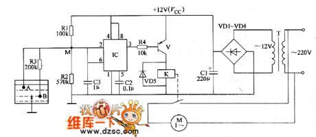
The agricultural automatical water feeder circuit is composed of the electrode A, electrode B, time-base integrated circuit IC, control transistor V, power transformer T, rectifier diodes VD1 ~ VD4 and relay K and other components, and the circuit is shown as the chart 1. AC 220V voltage is bucked by T, rectified by VD1 ~ VD4 and filtered by capacitor C1 to provide DC 12V voltage (Vcc) for IC as the operating voltage. R1 ~ R4 select l/4W or 1/8W carbon film resistors. Cl chooses the aluminum electrolytic capacitor with the voltage in 16V; C2 and C3 select monolithic capacitors. VD1 ~ VD5 use 1N4007 type silicon rectifier diodes. V uses C8050 silicon PNP transistor. K selects JRX-13F 12V DC relay.
Reprinted Url Of This Article:
http://www.seekic.com/circuit_diagram/Basic_Circuit/Agricultural_automatical_water_feeder_circuit_diagarm_13.html
Print this Page | Comments | Reading(3)

Article Categories
power supply circuit
Amplifier Circuit
Basic Circuit
LED and Light Circuit
Sensor Circuit
Signal Processing
Electrical Equipment Circuit
Control Circuit
Remote Control Circuit
A/D-D/A Converter Circuit
Audio Circuit
Measuring and Test Circuit
Communication Circuit
Computer-Related Circuit
555 Circuit
Automotive Circuit
Repairing Circuit
Code: