
Index 391
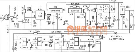
alarm system of cultural relics circuit
Published:2011/6/29 0:39:00 Author:chopper | Keyword: alarm system, cultural relics
View full Circuit Diagram | Comments | Reading(492)
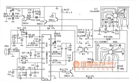
SNS-200P1R pyroelectric infrared alarm
Published:2011/6/29 0:56:00 Author:chopper | Keyword: pyroelectric, infrared alarm
View full Circuit Diagram | Comments | Reading(448)
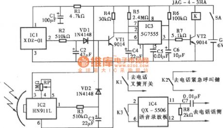
Security alarm telephone system circuit
Published:2011/6/29 0:57:00 Author:chopper | Keyword: Security alarm, telephone system
View full Circuit Diagram | Comments | Reading(481)
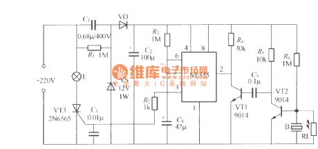
electric shock alarm circuit(3)
Published:2011/6/29 0:58:00 Author:chopper | Keyword: electric shock, alarm
View full Circuit Diagram | Comments | Reading(711)
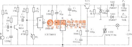
electric shock alarm circuit(2)
Published:2011/6/29 0:59:00 Author:chopper | Keyword: electric shock, alarm
View full Circuit Diagram | Comments | Reading(1148)
electric shock alarm circuit(1)
Published:2011/6/29 0:59:00 Author:chopper | Keyword: electric, shock alarm

View full Circuit Diagram | Comments | Reading(1219)
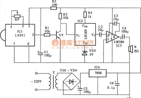
Electric sewing machine no-load economizer circuit diagram 1
Published:2011/6/13 5:12:00 Author:Lucas | Keyword: Electric , sewing machine, no-load , economizer
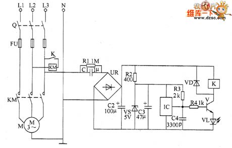
The electric sewing machine no-load economizer circuit is composed of the DC regulated power supply circuit, sensor control circuit and the main control circuit, and the circuit is shown as the chart. The DC regulated power supply circuit consists of step-down capacitor C1, drain resistor R1, bridge rectifier UR, filter capacitors C2 and C3, current limiting resistor R2 and Zener diode VS. Sensor control circuit is composed of the magnet and Hall sensor IC IC which are installed in the clutch lever of sewing machine (it includes the Hall element, differential amplifier, Schmitt trigger, and output circuit), resistors R3 and M, the capacitor C4, transistor V, diode VD, LED VL and relay K.
(View)
View full Circuit Diagram | Comments | Reading(1335)
Motor underloading energy saver circuit diagram 2
Published:2011/6/13 6:04:00 Author:Lucas | Keyword: Motor, underloading, energy saver
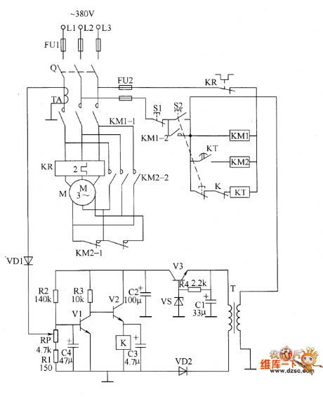
The motor underloading energy saver circuit is composed of the power supply circuit, power transformer T, voltage adjustment tube V3, voltage regulator diode VS, rectifier diode VD2, resistor R4 and filter capacitors C1 and C2 and so on. Current sampling detection circuit is composed of the current transformer TA, diode VD1, potentiometer RP, resistors R1 and R2, capacitor C4 and so on. Control circuit consists of the power switch Q, stop button S1, start button S2, transistors V1 and V2, relay K, time relay KT, AC contactors KM1 and KM2 and so on. R1 ~ R4 select 1/4W carbon film resistors. RP uses small potentiometer or variable resistor. C1 uses aluminium electrolytic capacitors with the voltage in 50V.
(View)
View full Circuit Diagram | Comments | Reading(1521)
Motor underloading energy saver circuit diagram 1
Published:2011/6/13 5:59:00 Author:Lucas | Keyword: Motor , underloading, energy saver
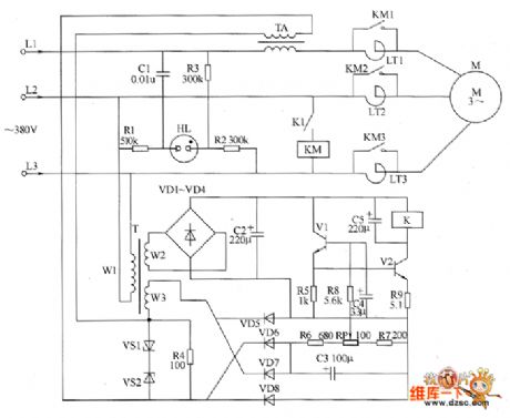
The motor underloading energy saver circuit is composed of the power supply circuit, current sampling circuit, phase sequence indication circuit, control amplifier circuit and other components, and the circuit is shown as the chart. Power supply circuit is composed of the power transformer T, rectifier diodes VD1 ~ VD4 and filter capacitor C2 and so on. Current sampling circuit consists of the current transformer TA, Zener diodes VS1 and VS2, resistor Ⅲ and diodes VD5 ~ VD8 and so on. Phase sequence indicating circuit is composed of the neon light HL, resistors R1 ~ R3, capacitor C1 and so on. Control amplifier circuit consists of the transistors V1 and V2, resistors R5 ~ R9, potentiometer RP, capacitors C4 and C5 and the relay K1 and so on. LT1 ~ LT3 are saturable reactors.
(View)
View full Circuit Diagram | Comments | Reading(1921)
The example circuit of the COB component
Published:2011/6/28 19:01:00 Author:TaoXi | Keyword: components, COB component
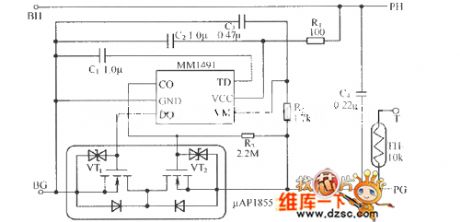
The COB(Chip On Board) component uses the circuit structure of the single lithium-ion battery protection component as the foundation, it is one kind of circuit form that encapsulates all of the components with the resin. The features of it are as shown: 1.Small volume and light weight. There is no need to install any metal wiring rack if the package has the integrated protection circuit and the naked chip FET component. 2.Water resisting property and insulating quality. Because the circuit component is sealed with the resin, so it has the water resisting property. 3. Reduces the fault in the secondary installation. The MM1491 is the single lithium-ion battery protection integrated circuit.
(View)
View full Circuit Diagram | Comments | Reading(614)
555 intermittent single tone audio circuit
Published:2011/6/15 21:25:00 Author:TaoXi | Keyword: 555, intermittent single tone, audio
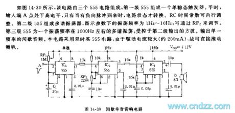
As the figure 14-30 shows, this circuit is composed of three 555 circuits, the first stage of 555 forms a monostable trigger. In peacetime, the input port A has the high electrical level, only when the negative pulse arrives, the circuit state will change. The RC time constant can be adjusted by itself. The second stage of 555 forms the multivibrator, the oscillation frequency of the figure parameter is 1Hz~10Hz, you can change it by adjusting RP2. The third stage of 555 is the multivibrator with the oscillation frequency of 1000Hz, it is controlled by the square wave. This circuit uses the double time base 555 circuit, because the drive current is large (about 200mA), so the current can drive the speaker directly.
(View)
View full Circuit Diagram | Comments | Reading(487)
High-Accuracy Pressure Amplifying Circuit Diagram
Published:2011/6/26 9:11:00 Author:Vicky | Keyword: High-Accuracy Pressure Amplifying
High-accuracy pressure amplifying circuit is mainly used in amplifying system of small sensor output signal. AD624 is amplifying circuit of high-accuracy low-noise instrument. The above picture is a high-accuracy amplifying circuit composed of AD624, and the sensor is a standard resistance straining bridge transducer. The bridge uses voltage of + 9.00V. Potentiometers R8 and R6 are used as zero setting. R6 is coarse regulation while R8 is fine regulation. The output of the amplifier can be connected to high-accuracy A/D converter directly. The number of amplifying time in the picture is 500. The signal can be amplified by a piece of AD624. (View)
View full Circuit Diagram | Comments | Reading(643)
F107 Double-Power General-Type Single-Supply Amplifier Circuit Diagram
Published:2011/6/26 9:16:00 Author:Vicky | Keyword: Double-Power General-Type Single-Supply
F107 series operational amplifier is a monolithic general-type inner complementing amplifier, with relatively low input current. It has no need of exterior complementing components, and is available in integrator, and sampling/maintaining low-frequency wave generator. The analog types or substitutions are F107MT、F207LT、F307CT、F107MD、F207LD、F307CD,Fl07MJ,F207LJ、F307CJ,F307CP,SM107,SG207,SG307,LMl07,LM207,LM307 etc. (View)
View full Circuit Diagram | Comments | Reading(696)
Non-two-wire system sound and light control stairs delay switch circuit(1)
Published:2011/6/27 22:50:00 Author:Ecco | Keyword: Non-two-wire , system , sound , light , control, stairs delay switch
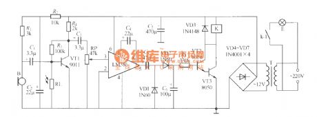
The use of two-wire connection, that is ,the switch only connects two external outgoing lines, so the installation is very convenient. Non-two-wire system sound and light control stairs delay switch circuit is shown as the chart, although the installation has too much trouble, the work has very good reliability, and in some cases it is still quite useful. In the Figure, K can use JZC-22F, DC12V small medium power relay, and T uses 220V/12V, 5VA small, high quality power transformer and other components are required as shown.
(View)
View full Circuit Diagram | Comments | Reading(507)
Non-two-wire system sound and light control stairs delay switch circuit(2)
Published:2011/6/27 22:53:00 Author:Ecco | Keyword: Non-two-wire , system , sound , light , control , stairs delay switch
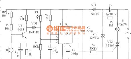
The chart shows the non-two-wire system sound and light control stairs delay switch circuit composed of NE555 time-base circuit, and it has the characteristics of precise delay time and so on.
(View)
View full Circuit Diagram | Comments | Reading(505)
Non-two-wire system sound and light control stairs delay switch circuit(3)
Published:2011/6/28 1:15:00 Author:Ecco | Keyword: Non-two-wire , system , sound , light , control, stairs delay switch
The chart shows the non-two-wire system sound and light control stairs delay switch circuit composed of NE555 time-base circuit, and it has the characteristics of good effect and simple circuit.
(View)
View full Circuit Diagram | Comments | Reading(508)
Non-two-wire system sound and light control stairs delay switch circuit(4)
Published:2011/6/28 1:21:00 Author:Ecco | Keyword: Non-two-wire , system , sound , light , control , stairs delay switch
The chart shows the non-two-wire system sound and light control stairs delay switch circuit composed of CD4011 digital IC and discrete components, and the circuit is characterized by strong anti-interference performance, stable and reliable work.
(View)
View full Circuit Diagram | Comments | Reading(563)
Non-two-wire system sound and light control stairs delay switch circuit(5)
Published:2011/6/28 1:25:00 Author:Ecco | Keyword: Non-two-wire , system , sound , light , control, stairs delay switch
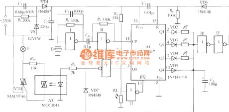
The chart shows the non-two-wire system sound and light control stairs delay switch circuit composed of CD4017, CD4069 and thyristor-type coupler, which is characterized by clapping number to choose different delay time.
(View)
View full Circuit Diagram | Comments | Reading(1204)
The electronic energy saving lamp maintenance circuit diagram
Published:2011/6/28 2:38:00 Author:Ecco | Keyword: electronic , energy saving lamp , maintenance


The saving lamp circuit has the glass cover type and exposed type. Glass cover types have three series of spherical, cylindrical ball, processing type, etc. , the first two series have completely four types of transparent, carving, engraving and white color. It has the advantages of beautiful appearance, easy installation, anti-collision, etc.; exposed type has the types of H, UH-based, 3U, 4U-based, 2D and screw type. They also can be divided by the color of light, which can be divided into red, green, blue, yellow (color temperature is 2700K, and it belons to warm light which is similar to incandescent light color), white (color temperature is 6400K, is a cool light which similar to fluorescent light color); the lamps with color temperature in 5000K has no irritation to the eyes as the light color close to natural light.
(View)
View full Circuit Diagram | Comments | Reading(4924)
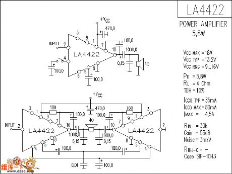
LA4422 audio IC circuit diagram
Published:2011/6/28 2:55:00 Author:Ecco | Keyword: audio IC
View full Circuit Diagram | Comments | Reading(2037)
| Pages:391/471 At 20381382383384385386387388389390391392393394395396397398399400Under 20 |
Circuit Categories
power supply circuit
Amplifier Circuit
Basic Circuit
LED and Light Circuit
Sensor Circuit
Signal Processing
Electrical Equipment Circuit
Control Circuit
Remote Control Circuit
A/D-D/A Converter Circuit
Audio Circuit
Measuring and Test Circuit
Communication Circuit
Computer-Related Circuit
555 Circuit
Automotive Circuit
Repairing Circuit