
Index 396
Five frequency-standard frequency standard circuit
Published:2011/6/26 20:38:00 Author:TaoXi | Keyword: Five frequency-standard, frequency standard circuit
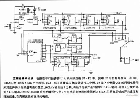
The five frequency-standard frequency standard circuit uses the DT direction cutting crystal in the NOT gate oscillator U1A and the divider chains U2-U6, and it produces the frequency standard at the frequencies of 200,100,50,25,10,5 kHz. The U2A-U3B are connected into the D trigger to produce the circuit of 2 frequency division. The U4 is the N frequency divider, the latch circuit of U5 can be used to reset the selective logic of 5 frequency division. The 100kHz output produces the symmetrical 10kHz output through the 5 and 2 frequency divisions, then the output changes into the 5kHz output through 2 frequency division. The CMOS CD4000 series logical components reduces the current of 9V battery to 2.8mA, but it still has enough switching speed and harmonic energy, and it has good phase reaction in the high frequency bands.
(View)
View full Circuit Diagram | Comments | Reading(552)
Pulse button control annular oscillator circuit
Published:2011/6/26 2:52:00 Author:TaoXi | Keyword: Pulse, button control, annular oscillator
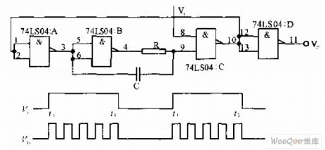
The pulse button control annular oscillator circuit is composed of the NAND gate. If the input Vi is the high level, the oscillator will start oscillating; if the Vi is low level, the oscillator will stop oscillating, the frequency of Vi is much lower than the oscillation frequency.
(View)
View full Circuit Diagram | Comments | Reading(496)
Adjustment application oscillator circuit
Published:2011/6/25 4:16:00 Author:TaoXi | Keyword: Adjustment application, oscillator circuit
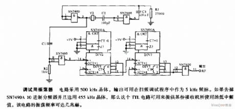
This circuit uses the 500kHz crystal, and its output can be used as the 5 kHz standard frequency in the frequency scanning debugging program. If you want to remove the SN7490A decimal divider and use the 455kHz crystal. so this TTL circuit can be used to supply the low frequency that are used by some receivers. The oscillation frequency of this circuit can be a few MHz.
(View)
View full Circuit Diagram | Comments | Reading(552)
Ultra low voltage white LED drive circuit
Published:2011/6/24 22:36:00 Author:TaoXi | Keyword: Ultra low voltage, white LED, drive circuit
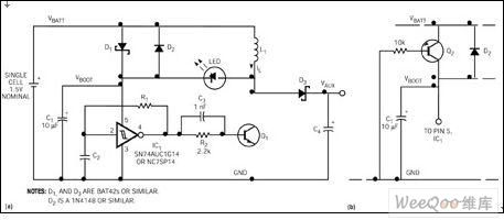
The positive voltage of the white LED is 3~5V, it is difficult that if we use only one battery to drive the white LED. This design uses the ultra-low operating voltage performance of the single-gate Schmitt inverter such as the 74HC14 or NC7SP14 (figure 1). When you add the battery power supply, the Schottky diode D1 conducts, the Schmitt trigger unsteady state multiple frequency oscillator starts working. The oscillation frequency depends on the timing components C2 and R1. When the output of IC1 is high level, the transistor Q1 conducts, the current of the inductor L1 increases gradually.
Figure 1 Ultra low voltage white LED drive circuit (View)
View full Circuit Diagram | Comments | Reading(515)
Jinbei RZH115LB a passenger vehicle circuit
Published:2011/6/24 10:34:00 Author:Fiona | Keyword: Jinbei RZH115LB, passenger vehicle
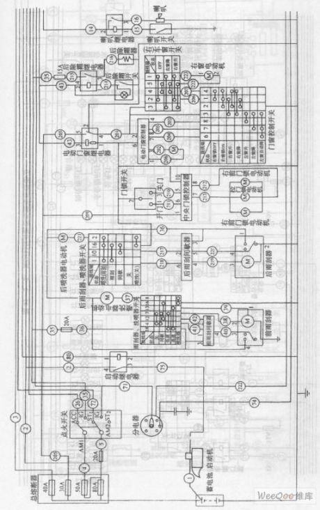
View full Circuit Diagram | Comments | Reading(471)
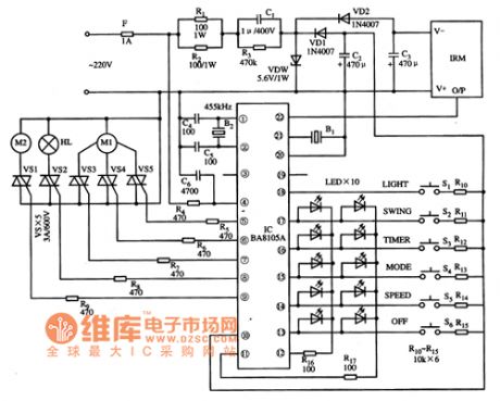
BA8105A fan single chip microcomputer integrated circuit
Published:2011/6/13 20:57:00 Author:Christina | Keyword: fan, single chip, microcomputer, integrated circuit
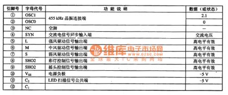
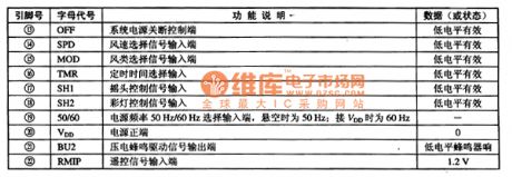
The BA8105A is designed as one kind of fan single chip microcomputer integrated circuit that is produced by the Toyo company, and it can be used in the program control system of various types of fan.
1.Features
The BA8105A is composed of the clock oscillating circuit, the button command decoding circuit, the speed control circuit, the remote control command signal processing circuit and other subsidiary function circuits.
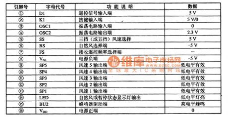
2.Pin functions and data
The BA8105A uses the 22-pin dual-row DIP package, the pin functions and data are as shown in table 1.
Table 1 The pin functions and data of the BA8105A
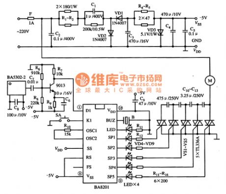
3.Typical application circuit
The operating voltage range of the BA8105A is 3.5 to 5V, the typical application circuit of the system is as shown in figure 1.
Figure 1 The typical application circuit of the BA8105A
Tips: The BA8105A can be used with the BA5102, and the infrared remote control multi-channel computer fan control circuit is composed of the BA8105A and the BA5102. (View)
View full Circuit Diagram | Comments | Reading(501)
BA8201 ceiling fan single chip microcomputer integrated circuit
Published:2011/6/13 21:04:00 Author:Christina | Keyword: ceiling fan, single chip, microcomputer, integrated circuit
The BA8201 is designed as one kind of ceiling fan single chip microcomputer integrated circuit that is produced by the Toyo company, and it can be used in the program control system of various types of ceiling fan.
The BA8201 uses the 16-pin dual-row DIP plastic package, the pin functions and data are as shown in table 1, the typical application circuit is as shown in figure 1.
Table 1 The pin functions and data of the BA8201
Figure 1 The typical application circuit of the BA8201
(View)
View full Circuit Diagram | Comments | Reading(672)
BA7201 air conditioner single chip microcomputer integrated circuit
Published:2011/6/13 21:22:00 Author:Christina | Keyword: air conditioner, single chip, microcomputer, integrated circuit
1.Features
The BA7201 is composed of the clock oscillating circuit, the reset circuit, the central processing unit (CPU), the infrared remote control signal decoding circuit, the compressor control circuit, the fan control circuit, the motor control circuit, the timing circuit, the AC zero-crossing circuit and other auxiliary function circuits.
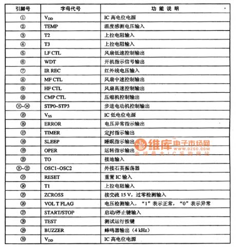
2.Pin functions
The BA7201 is in the 30-pin dual-row DIP package, the pin functions are as shown in the table 1.
Table 1 The pin functions of the BA7201(30PINSDIP)
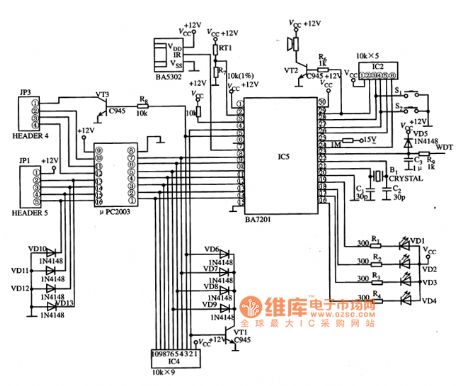
3.Typical application circuit
The control system typical application circuit which is composed of the BA7201 is as shown in figure 1.
Figure 1 The typical application circuit of the BA7201
(View)
View full Circuit Diagram | Comments | Reading(1635)
MIC4680 application circuit
Published:2011/6/13 21:55:00 Author:Christina | Keyword: application circuit
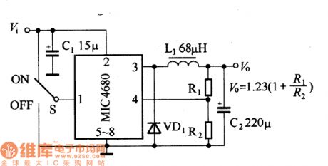
The adjustable output voltage circuit which is composed of the MIC4680 is as shown in the figure. The input voltage is 5 to 34V, the adjustable output voltage is decided by the R1 and R2.
The MIC4680 application circuit (View)
View full Circuit Diagram | Comments | Reading(606)
The protection circuit of IBA base power supply system
Published:2011/6/20 9:56:00 Author:Nancy | Keyword: IBA base power supply system, protection circuit
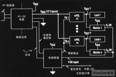
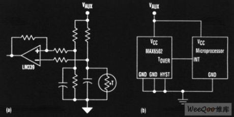
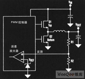
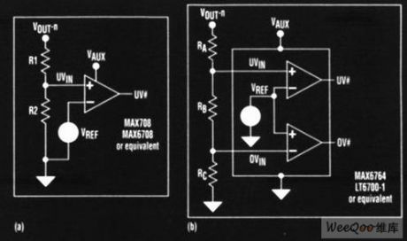
In many computer and communication applications, non-isolation load point (niPOL) Intermediate Bus Architecture (IBA) converter is replacing continuously the common distribution and central power supply system. The key drive force of the trend includes: the increase of the system power, higher output current, more strict regulated requirements and lower system cost, many IBA/niPOL solutions can meet these requirements. However,this solution don't have the protection mechanism included in the previous common solutions. In the power supply system design, over-voltage protection (OVP) and over-temperature protection is very expectable. (View)
View full Circuit Diagram | Comments | Reading(469)
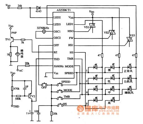
AX5206T1 and AX5206T3 fan single chip microcomputer integrated circuits
Published:2011/6/24 7:05:00 Author:Christina | Keyword: fan, single chip, microcomputer, integrated circuits
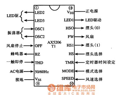
The AX5206T1 is designed as one kind of fan single chip microcomputer integrated circuit which is produced in TaiWan, it can be used in various kinds of fan program control circuits.
1.Pin functions
The AX5206T1 can be used with the single SCR, the AX5206T3 can be used with three SCRs, the pin functions of the AX5206T1 are as shown in figure 1.
Figure 1 The pin functions of the AX5206T1
2.Typical application circuit
The fan program control typical application circuit which is composed of the AX5206T1 is as shown in figure 2.
Figure 2 The typical application circuit of the AX5206T1
(View)
View full Circuit Diagram | Comments | Reading(477)
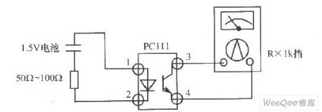
The photoelectric effect judgment circuit of photocoupler
Published:2011/6/20 8:33:00 Author:Nancy | Keyword: photocoupler, photoelectric effect
View full Circuit Diagram | Comments | Reading(524)
MIC4680-3.3BM application circuit
Published:2011/6/13 22:00:00 Author:Christina | Keyword: application circuit
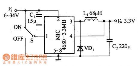
The fixed output voltage circuit which is composed of the MIC4680-3.3BM is as shown in the figure. The input voltage is 6 to 34V, the output voltage is 3.3V.
MIC4680-3.3BM application circuit (View)
View full Circuit Diagram | Comments | Reading(558)
MAX1745 application circuit
Published:2011/6/13 22:14:00 Author:Christina | Keyword: application circuit
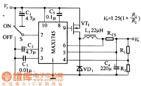
The typical application circuit of the MAXI745 is as shown in the figure, the input voltage is 5.5 to 36V, the input voltage is 1.25 to 18V, and the output voltage is decided by the partial pressure ratio of R1 and R2. The output current is decided by the current-limiting resistance RCS, and it also has relationship with the switch tube VT1 and the freewheeling diode VD1. The pin-7 of the MAX1745 can use the electrical level to close the power supply, in normal work, this pin can input the voltage Vi directly; if you want to close the power supply, you need to connect this port to ground.
MAX1745 application circuit (View)
View full Circuit Diagram | Comments | Reading(675)
BA6796FP servo driving integrated circuit
Published:2011/6/13 22:22:00 Author:Christina | Keyword: servo driving, integrated circuit
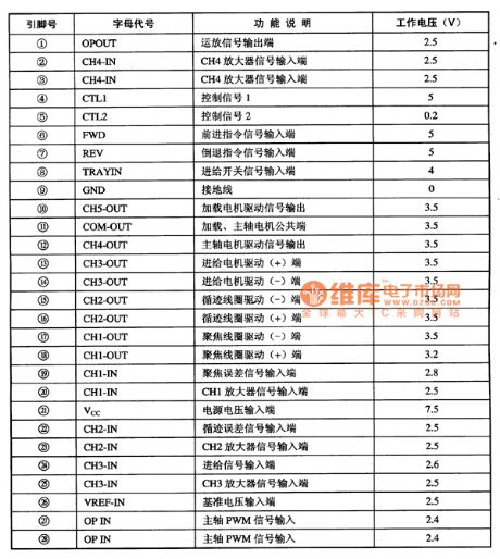
The BA6796FP is designed as one kind of servo driving integrated circuit that is produced by the Toyo company, and it can be used in the CD、VCD、SVCD、CVD、DVD.
1.Features
The BA6796FP has the 4-channel BTL driver, and it can change the laser head servo control voltage into the two-way driving voltage to drive the execution units of the servo mechanism.
2.Pin functions and data
The BA6796FP uses the 8-pin dual-row DIP package, the pin functions and data is as shown in table 1.
Table 1 The pin functions and data of the BA6796FP
(View)
View full Circuit Diagram | Comments | Reading(447)
MCU interface circuit
Published:2011/6/18 22:05:00 Author:Nancy | Keyword: MCU interface
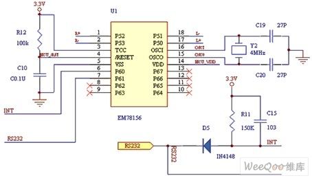
In the circuit, the L, L+ control the left motor PWM, the R, R+ control the right motor PWM. The RS232 receives coordinate data input of the sensor. IC operates at 3.3 V and resets automatically when power on. System clock uses 4MHz external crystal oscillators. (View)
View full Circuit Diagram | Comments | Reading(740)
PB5020/21/22 typical application circuit
Published:2011/6/14 1:26:00 Author:Christina | Keyword: typical application
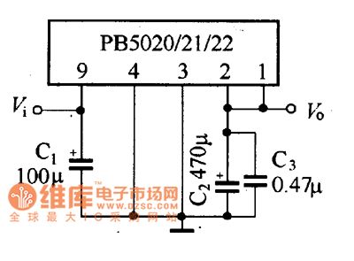
The PB5020/21/22 typical application circuit is as shown in the figure. This circuit has the features of less external components, wide input voltage range and it does not need to add the heat sink.
The MAX849 typical application circuit (View)
View full Circuit Diagram | Comments | Reading(479)
Touch screen interface circuit
Published:2011/6/18 21:58:00 Author:Nancy | Keyword: Touch screen, interface
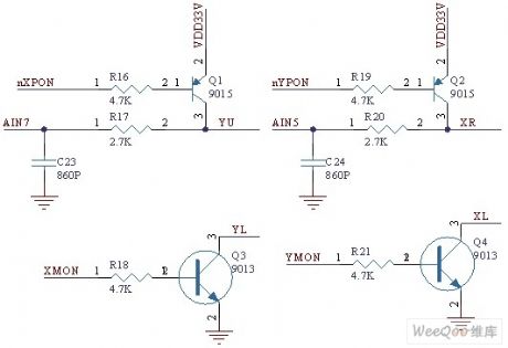
The man machine interface of vibration test analyzer uses resistance touch screen and 640×480 highlight TFT LCD, which makes the man machine interface friendly and operation simple. The S3C2410 is built with a touch screen interface circuit and the touch screen interface design is very simple. The touch screen interface circuit is shown as the figure, YU, YL, XR, XL represent the four interface signals of the resistance touch screen. (View)
View full Circuit Diagram | Comments | Reading(1401)
modulator circuit used to indicate low voltage high frequency signal
Published:2011/6/18 10:37:00 Author:Nancy | Keyword: low voltage high frequency signal, modulator circuit
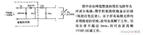
The voltage doubler circuit of peak rectification shown in the figure is used as test head circuit to control high ohm display loop (field effect voltmeter). Since all the high frequency components adopt very short lead, it can work under high frequency. The lead length can not exceed 2mm, then it can work under VHF area.
(View)
View full Circuit Diagram | Comments | Reading(407)
Charge pump multi-voltage output circuit composed of Walter Schottky diodes
Published:2011/6/19 10:36:00 Author:TaoXi | Keyword: Charge pump, multi-voltage, output circuit, Walter Schottky diodes
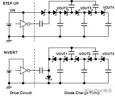
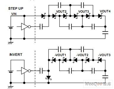
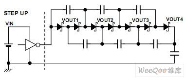
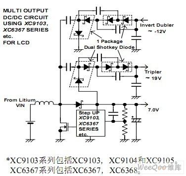
Circuit principle:
The basic circuit is as shown in figure 1.
The output voltage is as shown, the output voltage VOUT1, VOUT2, VOUT3 is the 1, 2, 3 times of the input voltage respectively. The rising voltage produces the N(>=2) times voltage by using the single power supply and the clock pulse; the reversal uses the clock pulse to produce the -N(>=1) times voltage.
Figure 2 is the changed circuit, the rising time of it is shorter than the basic circuit, but the stability is poor.
Figure 3 is the method which only uses the clock pulse to produce the rising voltage. Although you need to add some schottky diodes and capacitances in the circuit, but you do not need the single power supply.
Figure 4 is the multi-power application example which is composed of the figure 3 circuit. This design can be used in the PDA and LCD applications, because this device can produce multiple groups of positive and negative voltage output by using a single channel DC/DC converter, such as the 9103 series.
Figure 1 The basic circuit 1
Figure 2 The basic circuit 2
Figure 3 The voltage rising circuit which uses the clock pulse only
Figure 4 The application example of the multi-power
(View)
View full Circuit Diagram | Comments | Reading(1382)
| Pages:396/471 At 20381382383384385386387388389390391392393394395396397398399400Under 20 |
Circuit Categories
power supply circuit
Amplifier Circuit
Basic Circuit
LED and Light Circuit
Sensor Circuit
Signal Processing
Electrical Equipment Circuit
Control Circuit
Remote Control Circuit
A/D-D/A Converter Circuit
Audio Circuit
Measuring and Test Circuit
Communication Circuit
Computer-Related Circuit
555 Circuit
Automotive Circuit
Repairing Circuit