Position: Home > Circuit Diagram > Basic Circuit > modulator circuit used to indicate low voltage high frequency signal
Basic Circuit
modulator circuit used to indicate low voltage high frequency signal
Published:2011/6/18 10:37:00 Author:Nancy | Keyword: low voltage high frequency signal, modulator circuit | From:SeekIC
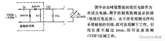
The voltage doubler circuit of peak rectification shown in the figure is used as test head circuit to control high ohm display loop (field effect voltmeter). Since all the high frequency components adopt very short lead, it can work under high frequency. The lead length can not exceed 2mm, then it can work under VHF area.
Reprinted Url Of This Article:
http://www.seekic.com/circuit_diagram/Basic_Circuit/modulator_circuit_used_to_indicate_low_voltage_high_frequency_signal.html
Print this Page | Comments | Reading(3)

Article Categories
power supply circuit
Amplifier Circuit
Basic Circuit
LED and Light Circuit
Sensor Circuit
Signal Processing
Electrical Equipment Circuit
Control Circuit
Remote Control Circuit
A/D-D/A Converter Circuit
Audio Circuit
Measuring and Test Circuit
Communication Circuit
Computer-Related Circuit
555 Circuit
Automotive Circuit
Repairing Circuit
Code: