
Index 385
Transfusion warmer 1
Published:2011/6/27 1:42:00 Author:Nicole | Keyword: Transfusion warmer
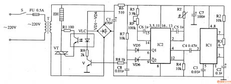
This transfusion warmer circuit is composed of astable multivibrator, temperature detector control circuit, heating circuit and power supply, it is shown in the figure 9-151.
The astable multivibrator is made of resistors R2, R3, capacitors C2, C3 and time base integrated circuit IC1.
The temperature detector control circuit consists of trigger integrated circuit IC2, thermal resistor RT, potentiometer RP, resistors R4, R5, R7-R9, capacitors C4-C6, transistor V and diodes VD5, VD6.
The heating circuit is composed of light clutch VLC, resistor R1, thyristor VT and heater EH.
(View)
View full Circuit Diagram | Comments | Reading(823)
Psychological stress alleviating 3
Published:2011/6/27 2:24:00 Author:Nicole | Keyword: psychological stress, alleviating
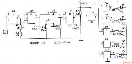
This psychological stress alleviating circuit is composed of low frequency oscillator, high frequency oscillator and not gate circuit, it is shown in the figure 9-150.
The low frequency oscillator is made of not gate integrated circuits D1, D2 and oher peripheral devices, the work frequency is 2-20Hz.
The high frequency oscillator consists of D3, D4 and oher peripheral devices, the work frequency is 1KHz.
The low frequency oscillator's frequency can be changed between 2-20Hz by adjusting potentiometer RP, then the flashing frequency of LEDs will be changed.
(View)
View full Circuit Diagram | Comments | Reading(706)
Psychological stress alleviating 2
Published:2011/6/27 2:16:00 Author:Nicole | Keyword: psychological stress, alleviating
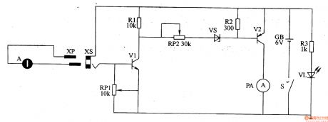
This psychological stress alleviating circuit is composed of power supply circuit, detection circuit and output circuit, it is shown in the figure 9-149.
The power supply circuit is made of power supply switch S, battery GB, current limiting resistor R3 and power supply indication LED VL.
The detection circuit consists of detection electrode A, plug XP, socket XS, potentiometer RP1 and transistor V1.
The output circuit is composed of resistors R1, R2, potentiometer RP2, Zener diode VS, transistor V2 and ammeter PA.
(View)
View full Circuit Diagram | Comments | Reading(437)
Motor brake
Published:2011/7/1 1:38:00 Author:Nicole | Keyword: motor, brake
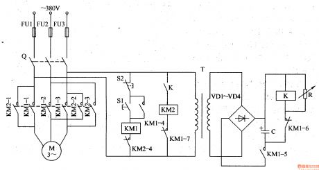
The motor brake circuit is composed of power transformer T, rectifier diode VD1-VM, changeable resistor R, capacitor C, relay K, AC contactor KM1, KM2 and starter button S1, stop button S2, it is shown in the figure 8-65.
After the starter button S1 is pressed, AC contactor KM1 works, the normally open contact KM1-1-KM1-5 is turned on, the normally closed contact KM1-6-KM1-7 is turned off, motor M runs, the power transformer T works too, after the induced voltage is rectified by VD1-VD4, it charges to capacitor C.
(View)
View full Circuit Diagram | Comments | Reading(1221)
Psychological stress alleviating 1
Published:2011/6/27 2:07:00 Author:Nicole | Keyword: psychological stress, alleviating
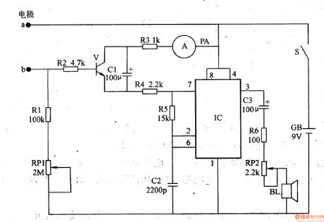
This psychological stress alleviating circuit is composed of skin resistance detection/indication circuit and audio circuit, it is shown in the figure 9-148.
The skin resistance detection/indication circuit is made of electrodes a, b, resistors R1-R4, potentiometer RP1, capacitor C1, transistor V and ammeter PA.
The audio circuit consists of time base integrated circuit IC, resistors R5, R6, capacitors C2, C3, volume potentiometer RP2 and loudspeaker BL. The monostable multivibrator circuit is composed of IC and R5.
After the power supply switch S is connected, GB provides the whole machine with 9V DC working voltage.
(View)
View full Circuit Diagram | Comments | Reading(1022)
Electronic snore-ceasing equipment 5
Published:2011/6/27 4:30:00 Author:Nicole | Keyword: Electronic snore-ceasing equipment
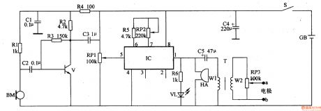
This electronic snore-ceasing equipment circuit is composed of power supply circuit, sound control circuit and electrical pulse generation circuit, it is shown in the figure 9-147.
The sound control circuit is made of microphone BM, resistors R1-R4, capacitors C1, C2 and transistor V.
The electrical pulse generation circuit consists of IC(Y976), resistor R5, potentiometers RP1-RP3, capacitors C3, C5, pulse transformer T and electrodes a,b.
After the power supply switch S is connected, GB's 3V DC voltage is filtered by C4, one path is fed to IC, the other path is current limited by R4 and it is as the working power of sound control circuit.
(View)
View full Circuit Diagram | Comments | Reading(534)
Electronic snore-ceasing equipment 4
Published:2011/6/27 4:15:00 Author:Nicole | Keyword: Electronic snore-ceasing equipment
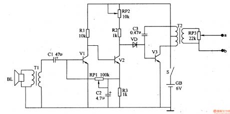
This snoring detection amplifier circuit is composed of loudspeaker BL, coupling transformer T1, capacitors C1, C2, audio amplifier transistors V1, V2, resistors R1-R3 and potentiometers RP1, RP2.
The pulse oscillator is made of diode VD, oscillation tube V3, capacitor C3, pulse transformer T2 and potentiometer RP3.
After the power supply switch S is connected, the snoring detection amplifier circuit starts to work. When there is no snoring, V2's collector has no audio voltage output, V3 is in off state, the electrodes a,b has no stimulation pulse output.
(View)
View full Circuit Diagram | Comments | Reading(521)
Electronic snore-ceasing equipment 3
Published:2011/6/27 4:05:00 Author:Nicole | Keyword: Electronic snore-ceasing equipment
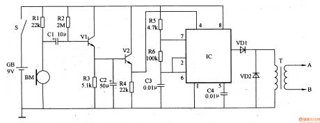
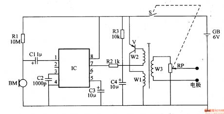
This electronic snore-ceasing equipment circuit is composed of audio detection circuit and stimulation pulse generator circuit.
The audio detection amplifier circuit is made of microphone BM, audio amplifier tubes V1, V2, capacitors C1, C2 and resistors R1-R4.
The stimulation pulse generator circuit consists of time base integrated circuit IC, resistors R5, R6, capacitors C3, C4, diodes VD1, VD2 and pulse transformer T.
After the power supply switch S is connected, this electronic snore-ceasing equipment's audio detection amplifier circuit starts to work.
(View)
View full Circuit Diagram | Comments | Reading(821)
Electric snore-ceasing equipment 1
Published:2011/6/30 22:36:00 Author:Nicole | Keyword: Electric snore-ceasing equipment
The electric snore-ceasing equipment circuit is composed of snoring detection control circuit and electricity pulse generation circuit, it is shown in the figure 9-143.
The snoring detection control circuit is made of microphone BM, audio level demodulation integrated circuit IC(NJM2027D) and peripheral resistor capacitor component.
NJM2027D contains operation amplifier, detector, electronic switch, Schmitt trigger, output buffer and constant current source, its pin function is: 1 foot is signal input terminal; 2 foot, 3 foot are gain control terminals; 4 foot is grounding terminal; 5 foot is recovery time control terminal; 6 foot, 7 foot are level output terminals; 8 foot is power supply terminal.
(View)
View full Circuit Diagram | Comments | Reading(867)
Macromolecule capacitive humidity sensor structure circuit
Published:2011/6/27 6:45:00 Author:Christina | Keyword: Macromolecule, capacitive, humidity sensor, structure circuit

The macromolecule capacitive humidity sensor structure circuit is as shown in the figure. This kind of humidity sensor is a capacitor, the electrode of the macromolecule film is a layer of very thin metal micropore evaporation film, the water molecules can be adsorbed or released by the macromolecule film through the electrodes of two ends, this makes the macromolecule film dielectric constant change. Because the dielectric constant changes with the relative air humidity, so we can get the relative humidity value by measuring the value of capacitance C. The capacitance value of the humidity sensitive component can be confirmed by the formula of C=εS/d.
(View)
View full Circuit Diagram | Comments | Reading(655)
Thermometer meter slinger 2
Published:2011/6/29 20:14:00 Author:Nicole | Keyword: thermometer, meter slinger

The thermometer meter slinger circuit is composed of power supply circuit and meter slinger timing control circuit, it is shown in the figure 9-135.
The power supply circuit is made of fuse FU, power supply button S(Sa, Sb), resistors R1, R2, capacitors C1, C2, power supply indication LED VL, steady voltage diode VS and rectifier diodes VD1.
The meter slinger timing control circuit consists of resistors R3, R4, potentiometer RP, capacitors C3-C5, relay K and diode VD2.
C3's charge time can be changed by adjusting RP, then it can control M's run time.
(View)
View full Circuit Diagram | Comments | Reading(1083)
Motor two-path insurance starter
Published:2011/7/3 21:42:00 Author:Nicole | Keyword: motor, insurance starter
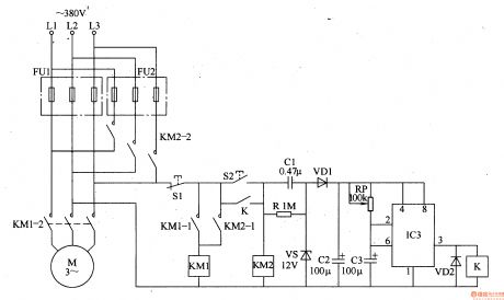
The motor two-path insurance starter circuit is composed of the first path fuse FU1, the second path fuse FU2, stop button S1, starter button S2, AC contactors KM1, KM2, relay K, capacitors C1-C3, diodes VD1, VD2, resistor R, steady voltage diode VS, potentiometer RP and time base integrated circuit IC, it is shown in the figure 8-57.
After IC works, due to the two sides of IC3's voltage can not be suddenly changed, IC's 2 foot, 6 foot are low level, 3 foot output is high level, K is pulled in, the normally open contact is turned on.
(View)
View full Circuit Diagram | Comments | Reading(541)
The Transistor AK90GB80 and AK90HB120 internal circuits
Published:2011/6/15 1:44:00 Author:Christina | Keyword: Transistor, internal circuit
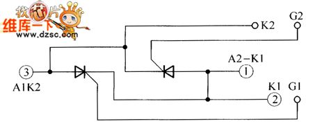
The Transistor AK90GB80 and AK90HB120 internal circuits:
(View)
View full Circuit Diagram | Comments | Reading(362)
Single Input CA3140 Instrument Amplifier Circuit
Published:2011/7/1 18:54:00 Author:Michel | Keyword: Single Input, Instrument Amplifier, Circuit
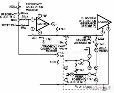
Picture:Single Input CA3140 Instrument Amplifier Circuit (View)
View full Circuit Diagram | Comments | Reading(826)
Shuangzhen Dalian Supplies Japan Anti-static Nylon Board
Published:2011/6/24 11:09:00 Author:Michel | Keyword: Shuangzhen Dalian , Japan, Anti-static, Nylon Board

Shuangzhen Dalian supplies Japan Importing anti-static nylon board.Shenzhen Shuangzhen Electronic Co., Ltd is found in Feb. 2007 which has office and warehouses. We are specialied in providing anti-static organic glasses.We devote to providing high-quality industrial products to meet the special needs of high-tech times industry and provide good after-sales service.
Features
MC501CDR6 the filling material of anti-static nylon board is even, anti-static value of all nylon parts are the same.Mechanical processing or after surface wearing, anti-static value has no change. (View)
View full Circuit Diagram | Comments | Reading(630)
EL display driving circuit composed of NE555
Published:2011/7/3 19:37:00 Author:Lucas | Keyword: EL display , driving circuit
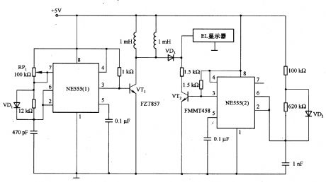
Light-emitting EL display has the advantages of long life (about l00OOh), light uniformity and low loss, and it is equivalent to the LCD for low-light-emitting display, which includs mobile phone, watch and automated meter display. The conventional EL drive circuit uses flyback converter to produce enough high-voltage EL light, if taking into account the cost of the converter and the space, this solution is too expensive. The advantage of EL display driver is that it is composed of low-loss NE555 and several switching transistors.
(View)
View full Circuit Diagram | Comments | Reading(2187)
The simple fluorescent lamp driver circuit
Published:2011/7/2 20:57:00 Author:Lucas | Keyword: simple, fluorescent lamp, driver circuit
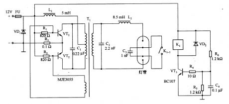
It is a self-excited push-pull converter which is conmposed of transformer and transistor. In the circuit, the transistor VT3, relay Kl, resistor R6 and capacitor C4 form the preheat circuit of fluorescent tube, and warm-up time is about 40Oms. When the relay Kl releases, then C3 is connected to the two ends of tube, it makes a certain voltage and current wave shape and increases the lamp power factor. Diode VDl and fuse FU are used to prevent reverse polarity voltage. Circuit switching frequency is about 25kHz, and its conversion efficiency is 75%.
(View)
View full Circuit Diagram | Comments | Reading(2150)
High voltage follower circuit
Published:2011/7/4 19:21:00 Author:Lucas | Keyword: High voltage, follower
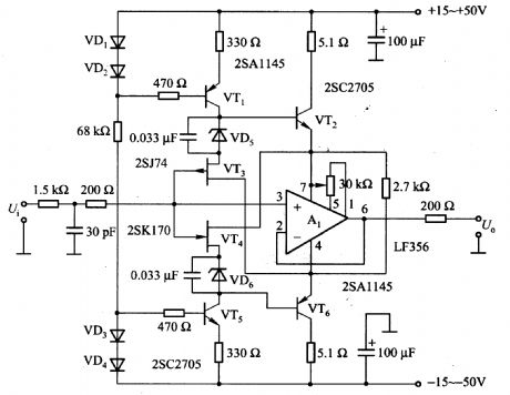
In the circuit, source follower circuit is composed of the VT3 and VT4, and Al is the voltage follower circuit, and the VT2 and VT6 connected to pin 7 and pin 4 of A1 form emitter follower circuit. The potential of pin 7 and pin 4 is the shifting of input signal voltage level, and therefore, the input signal is large, the voltage of output end and each power supply end keep constant with about 5V. As Al chip current signal flowing phase compensation capacitor is greatly improved, then the switching rate is increased and high-frequency distortion is greatly reduced.
(View)
View full Circuit Diagram | Comments | Reading(1479)
The wiring diagram of DC meter
Published:2011/6/26 21:10:00 Author:Ecco | Keyword: wiring diagram , DC meter
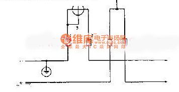
The DC circuit is generally tested by DC power meter. The common DC meter wiring method is shown as the chart. It has a voltage coil and a set of current coil, which are respectively connected in the tested circuit.
(View)
View full Circuit Diagram | Comments | Reading(517)
Philips Source Super Bass Loudspeaker Enclosure Power Amplifier Circuit
Published:2011/7/1 18:35:00 Author:Michel | Keyword: Philips, Source, Loudspeaker Enclosure, Power Amplifier, Circuit
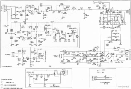
View full Circuit Diagram | Comments | Reading(3310)
| Pages:385/471 At 20381382383384385386387388389390391392393394395396397398399400Under 20 |
Circuit Categories
power supply circuit
Amplifier Circuit
Basic Circuit
LED and Light Circuit
Sensor Circuit
Signal Processing
Electrical Equipment Circuit
Control Circuit
Remote Control Circuit
A/D-D/A Converter Circuit
Audio Circuit
Measuring and Test Circuit
Communication Circuit
Computer-Related Circuit
555 Circuit
Automotive Circuit
Repairing Circuit