
Index 384
ND838 typical application circuit
Published:2011/7/5 20:43:00 Author:Christina | Keyword: typical application
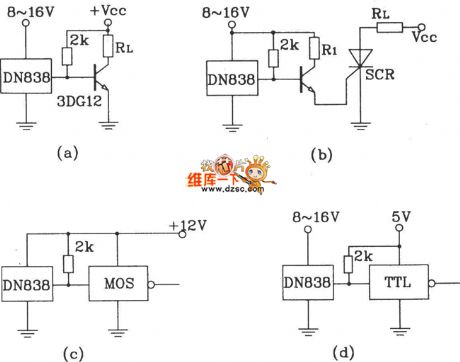
The outputs of figure (a), (b), (c), (d) can directly drive the transistor, the SCR, the relay, the CMOS circuit and the TTL circuit.
(View)
View full Circuit Diagram | Comments | Reading(436)
Benz ABS system component position circuit
Published:2011/7/5 19:01:00 Author:Christina | Keyword: Benz, ABS, system, component position
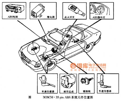
Benz ABS system component position circuit
Figure BOSCH-35pin ABS system component position circuit (View)
View full Circuit Diagram | Comments | Reading(908)
Benz LED light connection circuit
Published:2011/7/5 19:05:00 Author:Christina | Keyword: Benz, LED light, connection circuit
View full Circuit Diagram | Comments | Reading(1243)
1.5V power supply making circuit
Published:2011/7/5 19:42:00 Author:Christina | Keyword: 1.5V, power supply, making circuit

Some portable electronic devices such as the walkman and the MD often use the 1.5 V power supply. Some times you need to use the 1.5V power supply to replace battery. Here I introduce the 1.5V power supply circuit which is composed of the LM317T. This circuit is simple and has good performance, if you connect it according to the figure, you need not to debug it.
(View)
View full Circuit Diagram | Comments | Reading(2832)
Photosensitive resistor operating indication circuit
Published:2011/7/4 21:03:00 Author:Christina | Keyword: Photosensitive resistor, operating, indication circuit
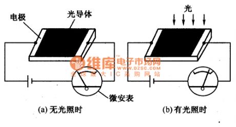
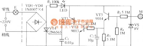
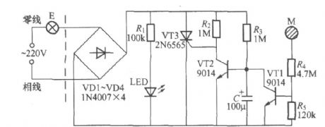
The working principle of the photosensitive resistor is the photoconductive effect. When the semiconductor materials are illuminated by the light, if the energy of the incident photons is larger than the prohibited bandwidth of the semiconductor, the number of the semiconductor internal carrier increases, so the conductivity of the semiconductor changes to reduce the resistance, this kind of physical phenomena is the photoconductive effect.
Figure: The Photosensitive resistor operating indication circuit
The photosensitive resistor in this figure has large resistance when there is no illumination, the resistance of it is in the range of 1 to 100MΩ. Because the resistance of the photosensitive resistor is too large, so the circuit current is small.
(View)
View full Circuit Diagram | Comments | Reading(539)
Quartz crystal resonator equivalent circuit
Published:2011/7/4 20:47:00 Author:Christina | Keyword: Quartz crystal, resonator, equivalent circuit
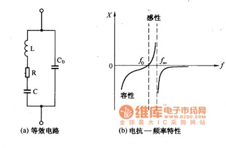
The quartz crystal resonator equivalent circuit and the characteristic curve are as shown in figure 1. In the equivalent circuit, C0 is the capacitance between the two electrodes when the quartz crystal is working, it is called the electrostatic capacitive. The L and C are the equivalent parameters when the quartz crystal is resonating, R is the equivalent resistance, it represents the friction loss when the quartz crystal is oscillating, its value is about 100 Ω.
Figure 1 The quartz crystal resonator equivalent circuit and the characteristic curve
From the quartz crystal reactance - frequency characteristic curve we can see, the quartz crystal has two inherent frequencies, one is the L, C series resonance frequency f0, another is the L, C, Co parallel resonant frequency f∞. Because the Co is one hundred times larger than C, so the frequency of it is decided by the L, C parameters. (View)
View full Circuit Diagram | Comments | Reading(1260)
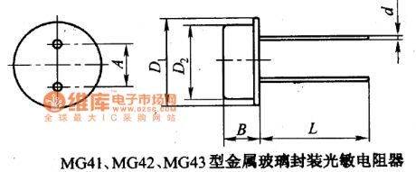
MG41, MG42, MG43 metal glass package photoconductive resistors circuit
Published:2011/7/4 20:36:00 Author:Christina | Keyword: metal, glass, package, photoconductive resistors
View full Circuit Diagram | Comments | Reading(452)
MG41, MG43 metal glass package double photoconductive resistors circuit
Published:2011/7/4 20:23:00 Author:Christina | Keyword: metal, glass, package, double photoconductive resistors

MG41, MG43 metal glass package double photoconductive resistors circuit (View)
View full Circuit Diagram | Comments | Reading(526)
Touching delay lamp switch circuit(4)
Published:2011/7/1 2:32:00 Author:Ecco | Keyword: Touching , delay lamp , switch
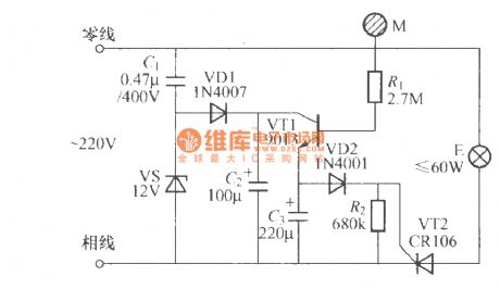
The chart shows the touching delay lamp switch circuit with two-wire connection, which is characterized by: the circuit design is reasonable, the individual discrete small, the delay time error between the manufactured goods is low, so it is suitable for the factory for mass production.
(View)
View full Circuit Diagram | Comments | Reading(588)
Touching delay lamp switch circuit(3)
Published:2011/7/1 2:22:00 Author:Ecco | Keyword: Touching , delay lamp , switch
View full Circuit Diagram | Comments | Reading(861)
Touching delay lamp switch circuit(2)
Published:2011/7/1 2:29:00 Author:Ecco | Keyword: Touching , delay lamp, switch
The chart shows the touching delay lamp switch circuit with two-wire connection, which can directly replace ordinary light switch without having to change the interior of the original wiring, so it is suitable for stairs or walkway lighting switches as they could be automatically turned off when going to bed at night. The relationship between C1 charge and discharge circuit and the delay time:
(View)
View full Circuit Diagram | Comments | Reading(685)
Touching delay lamp switch circuit(1)
Published:2011/7/1 2:26:00 Author:Ecco | Keyword: Touching , delay lamp, switch
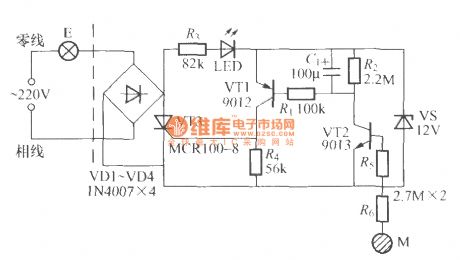
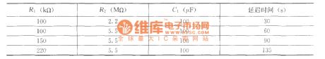
Touching delay lamp switch circuit is shown as the chart, as long as to touch the electrode M, the E will be lit, then after a short interval time, the light will automatically turn off. Using the icon data will make the delay time be about 90s. For extending the time, it is best to increase the capacity of C3; the other hand, it can reduce the C3 or the value of R2.
(View)
View full Circuit Diagram | Comments | Reading(524)
Bedside lamp safety switch circuit (3)
Published:2011/7/1 3:22:00 Author:Ecco | Keyword: Bedside lamp , safety switch
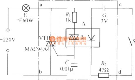
The circuit shown as the chart is bedside lamp safety switch which is composed of batteries and optical coupler, and it can completely isolate bedside switch S and AC, so security is very good.
(View)
View full Circuit Diagram | Comments | Reading(541)
Bedside lamp safety switch circuit (1)
Published:2011/7/1 3:27:00 Author:Ecco | Keyword: Bedside lamp , safety switch
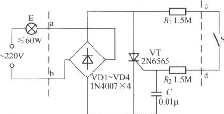
This switch can be directly connected to the power cord of bedside lamp in series, which is easy to use. But after using for a long time, broken power lines will cause accidents, if it uses the safety switch shown as the chart, you can boldly use. Closing switch S, thyristor VT can get the trigger current and open by R1, R2 and S, then the controlled lamp E is lit by geting the normal full-wave alternating current; turning on the switch S, VT will lose the gate trigger current, then light is off as AC is zero crossing.
(View)
View full Circuit Diagram | Comments | Reading(542)
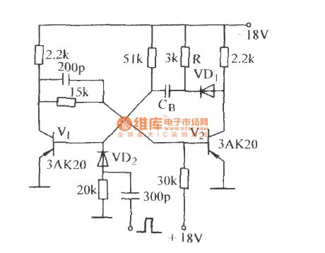
The high-speed single steady circuit (1)
Published:2011/7/4 4:03:00 Author:Borg | Keyword: high-speed, single steady circuit
View full Circuit Diagram | Comments | Reading(418)
Typical application circuit of the reference voltage source
Published:2011/6/27 6:43:00 Author:Christina | Keyword: Typical application, reference voltage source
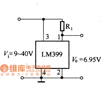
1.Typical application circuit of the LM399
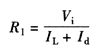
The typical application circuit of the LM399 integrated reference voltage source is as shown in the figure. In actual use, you can use it as the voltage-regulator tube, so when you connect it with the power supply voltage, you need to add the appropriate current-limiting resistance R1. The resistance of R1 can be calculated from this formula:
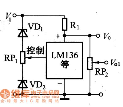
2.The typical application circuits of the LM136/236/336
The typical application circuits of the LM136/236/336 integrated reference voltage source are as shown in the figure.
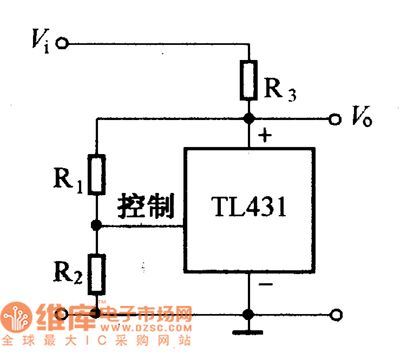
3.The typical application circuits of the TL431
The typical application circuits of the TM31 integrated reference voltage source are as shown in the figure.
The typical application circuit of LM399
The typical application circuit of LM136/236/336
The typical application circuit of TL431 (View)
View full Circuit Diagram | Comments | Reading(930)
Static electricity medical health care device
Published:2011/7/1 1:14:00 Author:Nicole | Keyword: Static electricity, medical health care device
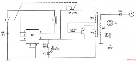
The static electricity medical health care device circuit is composed of DC boost circuit, high frequency oscillator and static electricity high voltage output circuit, it is shown in the figure 9-157.
The DC boost circuit is made of battery GB, power switch S, resistor R1, capacitor C, LED VL, boost integrated circuit IC and inductor L.
The high frequency oscillator circuit consists of transistor V, resistor R2, potentiometer RP and the winding W1, W2 of high voltage transformer T.
The static electricity high voltage output circuit is composed of T's winding W3, neon indicator light HL, resistor R3, rectifier diode VD and high voltage electrode A.
(View)
View full Circuit Diagram | Comments | Reading(1175)
Smoking telltale 2
Published:2011/6/27 1:20:00 Author:Nicole | Keyword: Smoking telltale
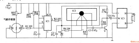
This smoking telltale circuit is composed of smog detector, monostable trigger, language generator and power amplifier circuit, it is shown in the figure 9-154.
The monostable trigger is made of time base integrated circuit IC1, resistor R2, capacitor C1 and potentiometer RP2.
The pronunciation generator circuit consists of language pronunciation integrated circuit IC2, resistors R3-R5, capacitor C2 and Zener diode VS.
The audio power amplifier circuit is composed of transistor V, boost power amplification module IC3, resistors R6, R7, capacitors C3, C4 and loudspeaker BL.
(View)
View full Circuit Diagram | Comments | Reading(510)
Smoking telltale 1
Published:2011/6/27 1:30:00 Author:Nicole | Keyword: Smoking telltale
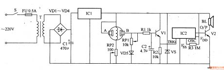
This smoking telltale circuit is composed of power supply, smog detector circuit and pronunciation circuit, it is shown in the figure 9-153.
The power supply is made of power supply transformer T, rectifier diodes VD1-VD4, filter capacitor C1 and three terminals integrated regulator IC1.
The smog detector circuit consists of gas sensitivity sensor, transistor V1 and other peripheral devices.
The pronunciation circuit is composed of pronunciation integrated circuit IC1(internal store the pronunciation Do not smoking pronunciation prompt), audio amplifier tube V2 and loudspeaker BL.
(View)
View full Circuit Diagram | Comments | Reading(515)
Transfusion warmer 2
Published:2011/6/27 1:53:00 Author:Nicole | Keyword: Transfusion warmer
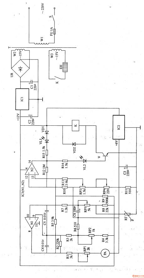
This transfusion warmer circuit is composed of power supply and temperature detector control circuit, it is shown in the figure 9-152.
The power supply circuit is made of power supply switch S, fuse FU, power transformer T, bridge rectifier UR, there terminals steady voltage integrated circuit IC1, IC2 and fliter capacitors C1-C3.
The temperature detector control circuit consists of thermal resistor RT, resistors R1-R5, potentiometers RP1-RP5, capacitors C4-C6, diodes VD1, VD2, LED VL1, VL2, transistor V, ammeter PA, relay K and operation amplifier integrated circuits IC3(N1, N2).
(View)
View full Circuit Diagram | Comments | Reading(508)
| Pages:384/471 At 20381382383384385386387388389390391392393394395396397398399400Under 20 |
Circuit Categories
power supply circuit
Amplifier Circuit
Basic Circuit
LED and Light Circuit
Sensor Circuit
Signal Processing
Electrical Equipment Circuit
Control Circuit
Remote Control Circuit
A/D-D/A Converter Circuit
Audio Circuit
Measuring and Test Circuit
Communication Circuit
Computer-Related Circuit
555 Circuit
Automotive Circuit
Repairing Circuit