
Index 414
Comparator Circuit
Published:2011/5/17 9:10:00 Author:Robert | Keyword: Comparator
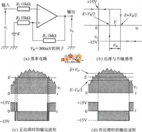
The Comparator Circuit is shown in the picture below. Picture (1) is basic circuit. Picture (2) is hysteresis and non-sensitive zone. Picture (3) is the output waveform with no hysteresis. Picture (4) is output waveform with hysteresis.
(View)
View full Circuit Diagram | Comments | Reading(651)
Current Flowing After Boot Circuit (2)
Published:2011/5/17 8:53:00 Author:Robert | Keyword: Current Flowing, Boot

The Current Flowing After Boot Circuit (2) is shown below.
(View)
View full Circuit Diagram | Comments | Reading(536)
TL494 Internal function block diagram and basic unit circuit diagram
Published:2011/5/15 8:47:00 Author:Rebekka | Keyword: Internal function block diagram, basic unit circuit
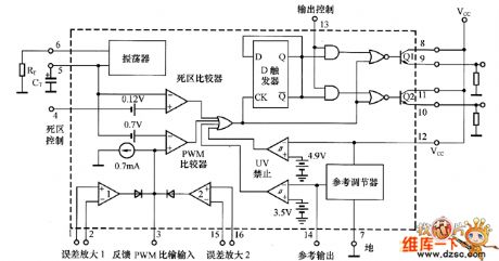
The system uses a PWM generator TL494 producd by Texas Instruments.It is a typical fixed-frequency PWM control IC, which contains all the required control switching power supply function. It can be used as a single-ended forward double tube, half bridge type, full bridge type switching power supply control system, the basic circuit units is shown as above. (View)
View full Circuit Diagram | Comments | Reading(3459)
Application input end zeroing circuit diagram
Published:2011/5/17 1:43:00 Author:Rebekka | Keyword: Application input end , zeroing circuit

In figure (a), it uses a small resistor R5 connecting in the return circuit of R1, the offset voltage produced by R5 and R3 are added to the left end of R1.And the voltage will be divided by R1 and R2. So the offset voltage adjustment range is determined by the following formula: Offset voltage adjustment range = ± VD · (R5/R3) · (R2 / (Rl + R2)) (± VD = ± l5V).
According to the resistance value shown in figure (a) , the offset voltage adjustment range is: ± 15mV. R1 = R2. Therefore, the voltage gain of the circuit is low. Taking the R5 and R1 are in series into account , the voltage gain Av: Av = 1 + R2 / (Rl + R5) (View)
View full Circuit Diagram | Comments | Reading(687)
Automatic hand dryer 4
Published:2011/5/16 21:54:00 Author:Nicole | Keyword: hand dryer
The circuit work theory
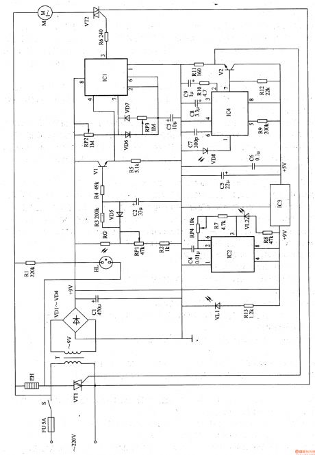
This automatic hand dryer circuit is composed of power supply, infrared transmitting circuit, infrared signal process circuit, electric heater circuit and fan control circuit, the circuit is shown in the figure 9-127.
The power supply circuit is made of fuse FU, power switch S, power transformer T, rectifier diodes VD1-VD4, filter capacitors C1, C5, C6, resistor R13, power indication LED VL1 and three terminal regulator integrated circuit IC3.
The infrared transmitting circuit is made of infrared LED VU, resistors R7, R8, capacitor RP4, capacitor C4 and time base integrated circuit IC2.
(View)
View full Circuit Diagram | Comments | Reading(1570)
Automatic hand dryer 1
Published:2011/5/16 21:25:00 Author:Nicole | Keyword: hand dryer
The circuit work theory
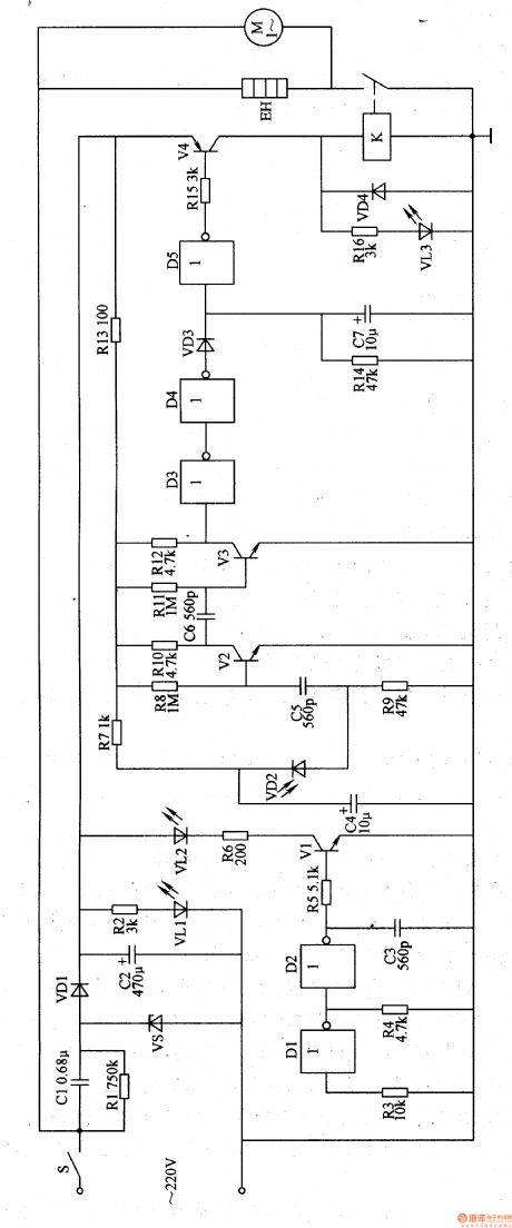
This infrared automatic hand dryer circuit is composed of power supply, infrared transmitting circuit, infrared receiving amplifier circuit, delay circuit and air heater control circuit, the circuit is shown in the figure 9-124.
The power supply is made of power supply switch S, depressurization capacitor C1, resistors R1, R2, voltage stabilizing diode VS, rectifier diode VD1, filter capacitor C2 and power indication LED VL1.
The infrared transmitting circuit is made of not gate integrated circuit IC(D1-D5) internal not gate D1, D2, resistors R3-R6, capacitor C3, transistor V1 and infrared LED VL2.
(View)
View full Circuit Diagram | Comments | Reading(858)
Automatic hand dryer 2
Published:2011/5/16 21:46:00 Author:Nicole | Keyword: hand dryer
The circuit work theory
This automatic hand dryer circuit is composed of power supply, infrared transmitting circuit, infrared receiving amplifier circuit, detector circuit and control circuit, the circuit is shown in the figure 9-125.
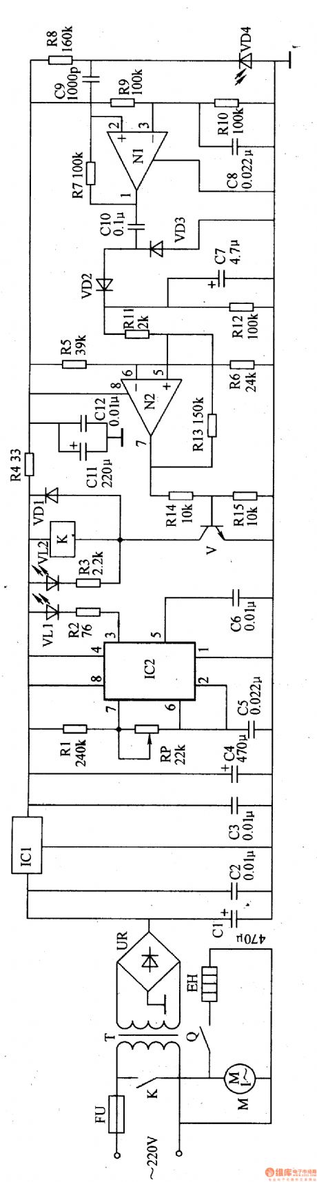
The power supply is made of fuse FU, power transformer T, bridge rectifier UR, filter capacitor C1-C4 and three terminal regulator integrated circuit IC1.
The infrared transmitting circuit consists of time base integrated circuit IC2, resistors R1, R2, capacitors C5, C6, potentiometer RP and infrared LED VL1.
The infrared receiving amplifier circuit is composed of infrared photosensitive diode VD4, resistors R7-RlO, capacitors C8, C9 and operational amplifier integrated circuit IC3(Nl、N2)internal N1.
(View)
View full Circuit Diagram | Comments | Reading(612)
Automatic hand dryer 3
Published:2011/5/16 21:46:00 Author:Nicole | Keyword: hand dryer

The circuit work theory
This automatic hand dryer circuit is composed of power supply, optical control circuit and control implement circuit, the circuit is shown in the figure 9-126.
The power supply circuit is made of depressurization capacitor C1, bleeder resistor R1, voltage stabilizing diode VS, rectifier diode UD1 and filter capacitor C2.
The optical control circuit is made of indicator light HL, light dependent resistor RG, resistor, capacitors C3, C4, potentiometer RP and time base integrated circuit IC.
The control implement circuit consists of relay K, diode VD2, heating wire EH and fan motor M.
(View)
View full Circuit Diagram | Comments | Reading(3445)
Automatic hand dryer 5
Published:2011/5/16 21:12:00 Author:Nicole | Keyword: hand dryer

The circuit work theory
This automatic hand dryer circuit is composed of power supply, infrared control circuit and hot air generation circuit, the circuit is shown in the figure 9-128.
The power supply is made of power supply switch S, depressurization capacitor C1, resistor R1, bridge rectifier UR1, filter capacitor C2 and voltage stabilizing diode VS.
The infrared control circuit consists of current limiting resistor R2, infrared LED VL, infrared photosensitive diode VD1, potentiometer RP, electronic switch integrated circuit IC, diode VD2 and relay K.
The hot air generation circuit is composed of K often open contact, heater EH, bridge rectifier UR2 and fan motor M.
(View)
View full Circuit Diagram | Comments | Reading(2764)
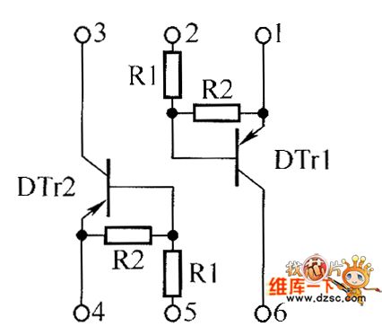
transistor UMD6N and EMD6 internal circuits
Published:2011/5/16 20:42:00 Author:Christina | Keyword: transistor, internal circuit
Thetransistor UMD6N and EMD6 internal circuits:
(View)
View full Circuit Diagram | Comments | Reading(387)
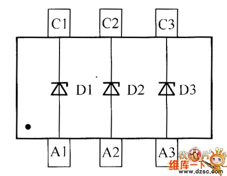
crystal diode DDZX9692TS internal circuit
Published:2011/5/15 6:17:00 Author:chopper | Keyword: crystal diode, internal circuit
View full Circuit Diagram | Comments | Reading(410)
crystal diode DDZX9693TS internal circuit
Published:2011/5/15 5:58:00 Author:chopper | Keyword: crystal diode, internal

View full Circuit Diagram | Comments | Reading(380)
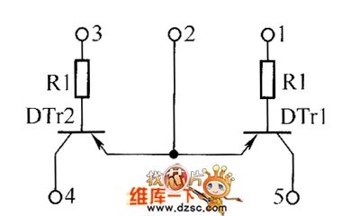
Transistor UMA1N internal circuit
Published:2011/5/17 2:34:00 Author:Christina | Keyword: Transistor, internal circuit

The Transistor UMA1N internal circuit is as shown:
(View)
View full Circuit Diagram | Comments | Reading(483)
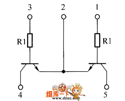
Transistor NUA2N, UMA5N, UMA5N, UMA9N internal circuits
Published:2011/5/17 2:32:00 Author:Christina | Keyword: Transistor, internal circuit

The Transistor NUA2N, UMA5N, UMA5N, UMA9N internal circuits are as shown:
(View)
View full Circuit Diagram | Comments | Reading(465)
Transistor UMA3N internal circuit
Published:2011/5/17 2:31:00 Author:Christina | Keyword: Transistor, internal circuit

The Transistor UMA3N internal circuit is as shown:
(View)
View full Circuit Diagram | Comments | Reading(429)
Transistor EMA3 and UMA4N internal circuits
Published:2011/5/17 2:30:00 Author:Christina | Keyword: Transistor, internal circuit
Transistor EMA3 and UMA4N internal circuits are as shown:
(View)
View full Circuit Diagram | Comments | Reading(508)
Transistor EMA4 internal circuit
Published:2011/5/17 1:37:00 Author:Christina | Keyword: Transistor, internal circuit

The Transistor EMA4 internal circuit is as shown:
(View)
View full Circuit Diagram | Comments | Reading(482)
Transistor UMB10N and EMB10 internal circuits
Published:2011/5/17 1:36:00 Author:Christina | Keyword: Transistor, internal circuit
The Transistor UMB10N and EMB10 internal circuits are as shown:
(View)
View full Circuit Diagram | Comments | Reading(500)
transistor UMB3N and EMB3 internal circuits
Published:2011/5/16 22:11:00 Author:Christina | Keyword: transistor, internal circuit

The transistor UMB3N and EMB3 internal circuits are as shown:
(View)
View full Circuit Diagram | Comments | Reading(470)
transistor UMG4N and EMG4 internal circuits
Published:2011/5/16 19:23:00 Author:Christina | Keyword: transistor, internal circuit
The transistor UMG4N and EMG4 internal circuits are as shown:
(View)
View full Circuit Diagram | Comments | Reading(511)
| Pages:414/471 At 20401402403404405406407408409410411412413414415416417418419420Under 20 |
Circuit Categories
power supply circuit
Amplifier Circuit
Basic Circuit
LED and Light Circuit
Sensor Circuit
Signal Processing
Electrical Equipment Circuit
Control Circuit
Remote Control Circuit
A/D-D/A Converter Circuit
Audio Circuit
Measuring and Test Circuit
Communication Circuit
Computer-Related Circuit
555 Circuit
Automotive Circuit
Repairing Circuit