Basic Circuit
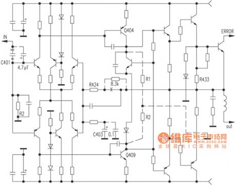
Improving sound quality of F15 power amplifier circuit diagram
Published:2011/5/17 21:21:00 Author:Ecco | Keyword: Improving , sound quality , power amplifier | From:SeekIC

According to the figure, this is a fully symmetrical, full complement, double differential circuit. Firstly, the C401 10μF ordinary electrolytic input capacitor should be replaced by a 4.7μF CBB capacitor; then both ends of the feedback blocking capacitor C403 are added the WIMA 0.1μF capacitor, this would obviously make the sound be more smooth and clear; the second step, for improving the open-loop instructions, motivation level Q404, Q409 should be added 10kΩ collector load resistors R1, R2, while the feedback resistor R424 is connected a 8.3kΩ resistor in series, this can give a more natural sound with better transient, while the gain does not decrease and increase slightly.
Reprinted Url Of This Article:
http://www.seekic.com/circuit_diagram/Basic_Circuit/Improving_sound_quality_of_F15_power_amplifier_circuit_diagram.html
Print this Page | Comments | Reading(3)

Article Categories
power supply circuit
Amplifier Circuit
Basic Circuit
LED and Light Circuit
Sensor Circuit
Signal Processing
Electrical Equipment Circuit
Control Circuit
Remote Control Circuit
A/D-D/A Converter Circuit
Audio Circuit
Measuring and Test Circuit
Communication Circuit
Computer-Related Circuit
555 Circuit
Automotive Circuit
Repairing Circuit
Code: