Basic Circuit
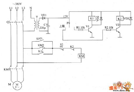
Electronic pressure switch circuit diagram
Published:2011/5/29 2:35:00 Author:Lucas | Keyword: Electronic pressure switch | From:SeekIC

The electronic pressure switch circuit consists of the power circuit and pressure detection control circuit, the circuit is shown as the chart. Power circuit is composed of the power transformer T, rectifier diode VD1 and filter capacitor C. Pressure detection control circuit consists of the electric contact pressure gauge P, resistors R1 and R2, transistors V1 and V2, the relays K1 and K2, and diodes VD2, VD3. M is the air compressor motor, KM is the exchange of contact, Q is the knife switch, S1 is the start button, S2 is the stop button. The AC voltage between phase line L3 and zero line bucked by T, rectified by VD1 and filtered by C can provide 12V DC voltage for K1 and K2. R1 and R2 use 1/4W metal film resistors, or carbon film resistors. C uses aluminium electrolytic capacitor with voltage in 16V. VD1 ~ VD3 use 1N4007 silicon rectifier diodes. V1 and V2 use S8050, C8050 or 3DG8050 silicon NPN transistors.
Reprinted Url Of This Article:
http://www.seekic.com/circuit_diagram/Basic_Circuit/Electronic_pressure_switch_circuit_diagram.html
Print this Page | Comments | Reading(3)

Article Categories
power supply circuit
Amplifier Circuit
Basic Circuit
LED and Light Circuit
Sensor Circuit
Signal Processing
Electrical Equipment Circuit
Control Circuit
Remote Control Circuit
A/D-D/A Converter Circuit
Audio Circuit
Measuring and Test Circuit
Communication Circuit
Computer-Related Circuit
555 Circuit
Automotive Circuit
Repairing Circuit
Code: