
Automotive Circuit
Index 79
TC9028P-012 and TC9028F-012 --The single chip remote emitter integrated circuit
Published:2011/6/7 2:12:00 Author:qqtang | Keyword: single chip, remote emitter
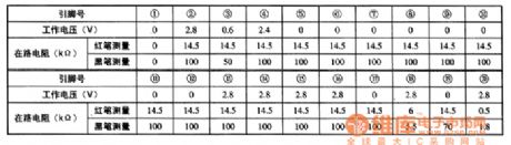
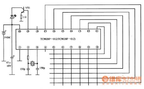
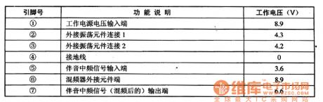
TC9028F-012 is the single chip remote emitter integrated circuit produced by Toshiba, which is widely used in systems of TV, stereos, disc players, air-conditioners and so on.1.function featuresTC9028F-012 contains the clock oscillator circuit, key scanning pulse generator, remote order encoder, signal emitting pre-amplifier circuit, measuring circuit and other additional circuit, etc.2.pin functions and dataTC9028F-012 is in 20-pin dual in-line package, whose pin functions are as follows:2-pin and 3-pin clock oscillating circuits connect with the element connectors.
(View)
View full Circuit Diagram | Comments | Reading(384)
Transformer feedback oscillator circuit
Published:2011/6/4 11:18:00 Author:John | Keyword: Transformer, oscillator
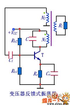
The easiest way to introduce positive feedback is to use transformer feedback method, just as shown in the figure. Replace the input voltage of the feedback voltage. And transformer feedback oscillator circuit is achieved.
Circuit Analysis: ★ Observe the circuit to find that there are amplifier, frequency selective network, positive feedback network and amplitude part achieved by nonlinear characteristics of used transistors;★ Determine whether amplifier circuit is normal or not. Amplification circuit shown in the circuit is the typical operating point stabilizing circuit, which can be used to set the appropriate static operating point; ★ Exchange pathway shown in the figure indicates that there is no open or short circuit during the signal exchanging process. And the circuit can be amplified normally;★ Use instantaneous polarity method to determine whether the circuit is able to meet equilibrium conditions or not (specific approach). (View)
View full Circuit Diagram | Comments | Reading(1243)
Capacitor feedback oscillator improved circuit
Published:2011/6/4 11:53:00 Author:John | Keyword: Capacitor, feedback oscillator
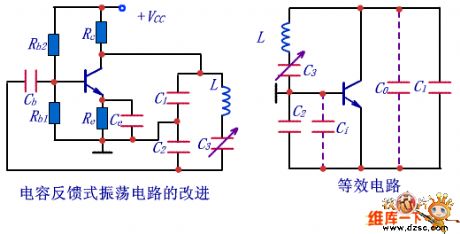
To increase the frequency of capacitor feedback oscillator circuit, it is necessary to reduce capacitance of C1 and C2 and L’s inductance. In fact, when capacitance of C1 and C2 is reduced to a certain extent, capacitor within transistor and the stray capacitors in the circuit will be incorporated into C1 and C2. Thus, the oscillator frequency can be affected. These capacitors are equivalent to input capacitor Ci and output capacitor Co in amplification circuit. The improved circuit and equivalent electrical device are shown below. Due to critical effect on capacitance by temperature and unsteady stray capacitors, it is necessary to serially set a capacitor C3 with small capacitance in the inductor branch circuit in order to stabilize the oscillation frequency. And C3 < <C1 and C3<<C2. (View)
View full Circuit Diagram | Comments | Reading(434)
adjustable frequency selection network circuit
Published:2011/6/4 12:08:00 Author:John | Keyword: selection network
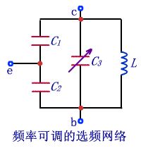
Output voltage of the capacitor feedback oscillator circuit has a good waveform. But if the oscillation frequency is adjusted by changing the capacitance, the feedback factors and the starting conditions for the circuit would be affected. And it is rather difficult to adjust the oscillation frequency by changing the inductance method. It is generally used occasions within a fixed oscillation frequency. When oscillation frequency is adjustable within a not wide range, the circuit as shown in the right figure can be used as a frequency selection network circuit. (View)
View full Circuit Diagram | Comments | Reading(393)
ASIC MM5369 circuit
Published:2011/6/4 9:07:00 Author:John | Keyword: ASIC
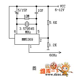
60Hz pulse circuit is formed by a 60Hz pulse generator ASIC MM5369 (pin 8 with DIP package) and the crystal with resonant frequency of 3.579545. It is used to provide support with the digital clock with frequency of 60Hz.
Oscillator signal is frequency processed through inner parts of MM5369. Such signal outputs from pin 1 with a rather stable frequency. The circuit is powered by 6 ~ 12V voltage. When the supply voltage is less than 6V, the operational reliability would be worse. Under special circumstances, the resistance of R3 in the circuit can be adjusted at about 100 ohms. Therefore, the normal operating voltage of the circuit is reduced to 4.5V.
(View)
View full Circuit Diagram | Comments | Reading(1877)
Single-tube mosquito lamp circuit
Published:2011/6/4 9:42:00 Author:John | Keyword: mosquito lamp
Single-tube mosquito lamp circuit is shown below.
(View)
View full Circuit Diagram | Comments | Reading(610)
binary serial counter / divider circuit
Published:2011/6/4 9:49:00 Author:John | Keyword: binary serial counter, divider
Circuit shown in figure 1 is constituted by a binary serial counter from 12 / divider and 60Hz digital time base circuit with six-inverter CD4069.
(View)
View full Circuit Diagram | Comments | Reading(1429)
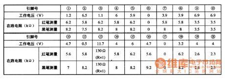
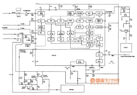
TA8844N--the brightness/chroma and scanning integrated circuit
Published:2011/6/8 4:23:00 Author:qqtang | Keyword: brightness/chroma, integrated circuit
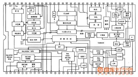
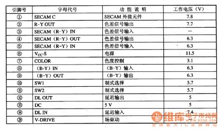
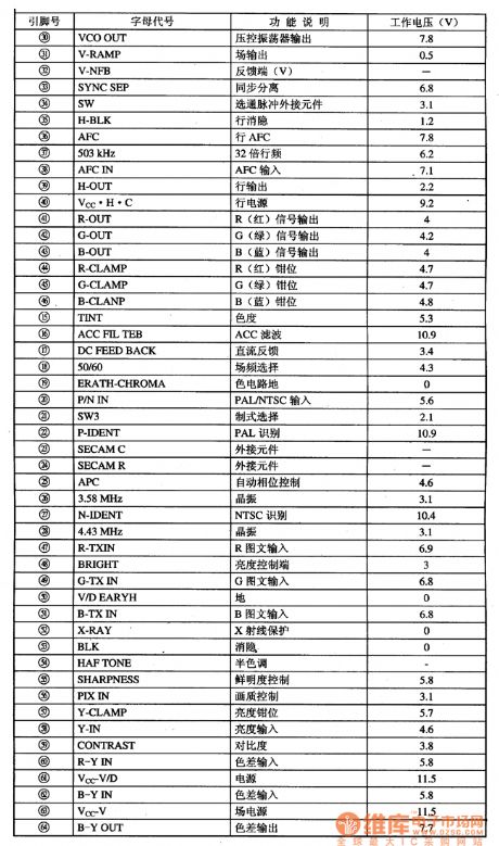
TA8844N is the brightness/chroma and scanning integrated circuit produced by Toshiba, which is widely used in large screen color TV sets.1.function featuresTA8844N is manufactured for large screen color TV sets, which contains the brightness signal process circuit, picture quality changing circuit, text signal process circuit, chroma signal process circuit, PAL/NTSC/SECAM switch and type recognizing circuit, travelling field scanning small signal process circuit and other additional circuits. Its internal circuit is shown in Figure1.
2.pin functions and data
(View)
View full Circuit Diagram | Comments | Reading(616)
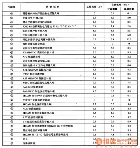
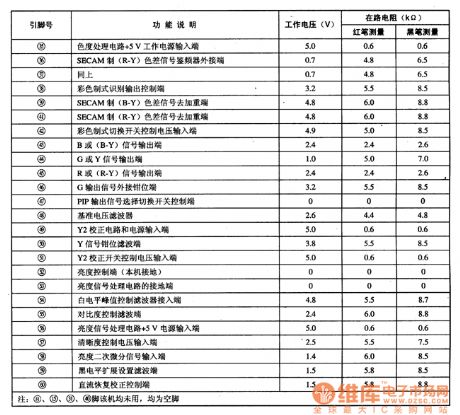
TA8814N--the integrated circuit of color transient characteristic improving
Published:2011/6/8 4:36:00 Author:qqtang | Keyword: integrated circuit, color, transient characteristic
1.function featuresTA8814N contains the pulse generator, clamper, time delay circuit, all kinds of amplifiers, phase inverter, mode selecting switch, gain control, Y adjusting circuit, adder and other additional circuits.2.the internal circuit, pin functions and typical application circuitTA8814N is in 20-pin dual in-line package, whose internal circuit, pin functions and typical application circuit are shown in figure 1.3. Tested typical dataThe tested typical working parameters of TA8814N are listed in Table 1 for reference.
(View)
View full Circuit Diagram | Comments | Reading(430)
TA8795AF--the integrated circuit of the sub-image multi-system brightness/chroma/synchronized signal process
Published:2011/6/8 6:24:00 Author:qqtang | Keyword: sub-image, multi-system, synchronized signal
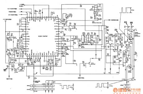
TA8795AF is an integrated circuit of the sub-image multi-system brightness/chroma/synchronized signal process, which is widely used in Toshiba large screen PIP color TV cores, such as Changhong NC-3 core, etc.1.function featuresTA8795AF includes the brightness signal process circuit, chroma signal process circuit, synchronized signal process circuit, all kinds of switches and relevant aid circuits.2.pin functions and dataTA8795AF is in 60-pin square package.
3.typical application circuit
(View)
View full Circuit Diagram | Comments | Reading(517)
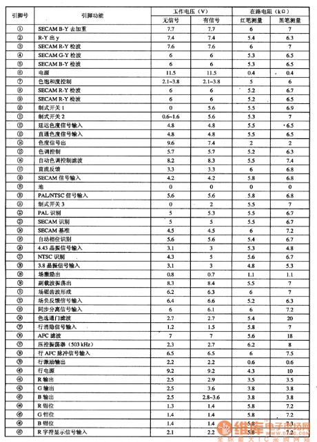
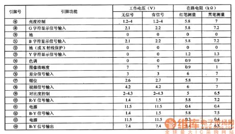
TA8783N--The brightness/chroma/bias process integrated circuit
Published:2011/6/8 6:38:00 Author:qqtang | Keyword: brightness/chroma/bias process, integrated circuit
1.function featuresTA8783N includes sub-circuits of the PAL/NTSC chroma signal process, brightness signal process, matrix converting, synchronized separation, 32fH line frequency oscillator, sandcastle pulse generating, travelling field motivating pulse generating, etc, which is under the control of CPU. Whether the circuit can come into work depends on whether CPU brings a right data general signal.2.pin functions and dataTA8783 is in 64-pin package, whose pin functions are shown in Table 1, and its working parameters are listed in Figure 2.
(View)
View full Circuit Diagram | Comments | Reading(5099)
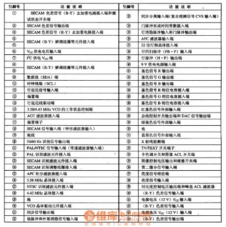
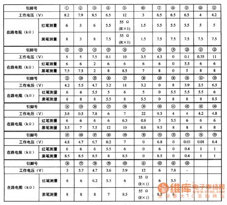
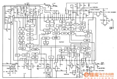
TA8765N-SECABM--the decoding integrated circuit
Published:2011/6/8 6:55:00 Author:qqtang | Keyword: decoding, integrated circuit
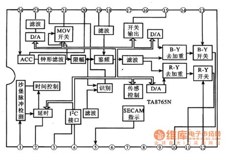
TA8765N —SECABM is the decoding integrated circuit produced by Toshiba, which is widely used in local and imported large screen multi-system color TV, such as Changhong NC-6 core.1.function featuresTA8765N —SECABM includes the sand castle signal process circuit, I2C general connector circuit, system recognition and output circuit, chroma signal frequency discrimination APC filter circuit, ACC filter circuit, switch output circuit, MOV switch circuit, D/A converting circuit and other additional function circuit,etc. Its internal circuit is in Figure 1.
(View)
View full Circuit Diagram | Comments | Reading(551)
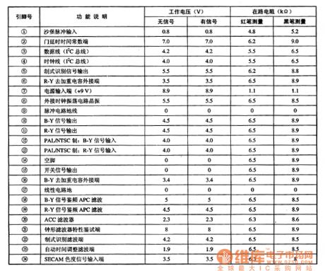
TA8759AN--the brightness/chroma/travelling field scanning integrated circuit
Published:2011/6/8 7:45:00 Author:qqtang | Keyword: travelling field, integrated circuit
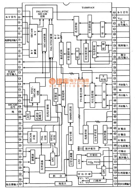
1.function featuresTA8759AN includes the video brightness and chroma signal process circuit, travelling field scanning small signal process circuit, 3 base color signal preset circuit, PAL/NTSC/SECAM system shifting control circuit, external text circuit signal connector circuit, X ray protection circuit, 3 system chroma signal preset circuit and other corresponding additional function circuit,etc.
2.pin function and dataTA8759AN is in 64-pin dual in-line package, whose pin functions and data are listed in table 1.
(View)
View full Circuit Diagram | Comments | Reading(965)
TA8719N--the decoding and travelling field scan integrated circuit
Published:2011/6/8 8:04:00 Author:qqtang | Keyword: travelling field, integrated circuit
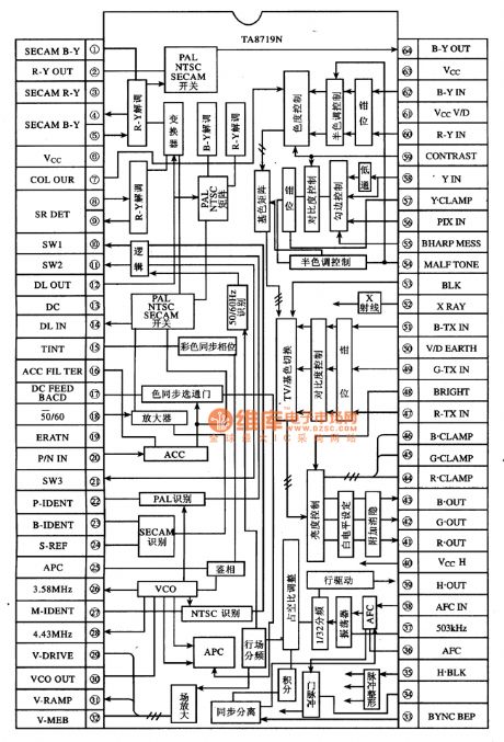
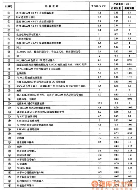
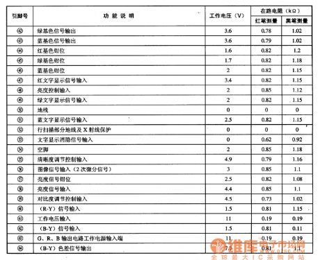
1.function featuresTA8719N has functions of PAL, NTSC, CECAM system decoding, travelling scanning small signal process and X ray protection, etc. Its internal circuit includes PAL、NTSC and SECAM switch, color variation modulation circuit, PAL and NTSC matrix system recognition circuit, travelling field scanning small signal process circuit, brightness and contrast ratio control circuit, chroma control circuit, synchronized separation circuit and APC and VCO circuit,etc.The internal circuit of TA8719N is shown in figure 1.
(View)
View full Circuit Diagram | Comments | Reading(514)
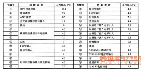
TA8710S--the sound IF mixing integrated circuit
Published:2011/6/8 19:54:00 Author:qqtang | Keyword: sound IF mixing, integrated circuit
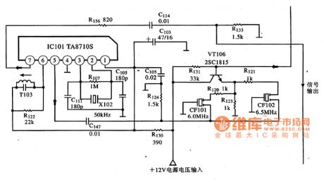
TA8710S is a sound IF mixing integrated circuit produced by Toshiba, which is widely used in multi-system large screen color TV.1.function features and typical application circuitTA8710S contains the sound IF mixing circuit and clock oscillating circuit, which is used to process 6MHz and 6.5MHz sound IF signals. Its typical application circuit is shown in figure 1.Figure 1 the typical application circuit of TA8710S
2.pin functions and dataTA8710S is in 7-pin in-line package, whose pin functions and data are listed in table 1.
(View)
View full Circuit Diagram | Comments | Reading(1919)
TA8662N--the NICAM short wave generator integrated circuit
Published:2011/6/8 20:05:00 Author:qqtang | Keyword: NICAM, short wave generator

TA8662N is a TA8662N short wave generator integrated circuit produced by Toshiba, which is used in large screen color TV and other stereo systems as the modulator.1.function featuresTA8662N contains sub-circuits of ACC detection, carrier frequency voltage control oscillator, parallel/serial converter, SHP generator, APC phase identifier, timed voltage control oscillator, differential converting circuit, silence/mute detection circuit, amplitude rectifier pulse frequency distributor, and so on. Its internal circuit is in Figure 1.
2.pin functions and data
(View)
View full Circuit Diagram | Comments | Reading(1270)
TA8402F--the motor drive integrated circuit
Published:2011/6/8 20:22:00 Author:qqtang | Keyword: motor drive, integrated circuit
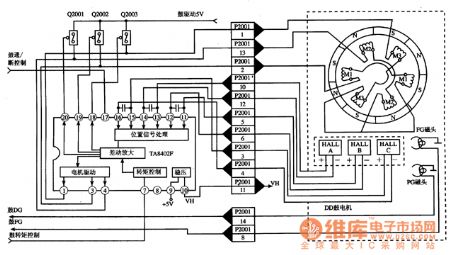
TA8402F is the motor drive integrated circuit produced by Toshiba, which is widely used in disc players and cameras, such as Panasonic NV-M8000 camera and the like.1.function featuresTA8402F contains the difference amplifier circuit, torque control circuit, position signal process circuit, motor drive circuit and stable voltage circuit, etc. The internal circuit and its typical application circuit are shown in figure 1.Figure 1. The internal circuit and typical application circuit of TA8402F
2.pin functions and dataThe pin functions and data are listed in table 1.
(View)
View full Circuit Diagram | Comments | Reading(628)
Asymmetrical multivibrator circuit
Published:2011/6/4 13:25:00 Author:John | Keyword: Asymmetrical multivibrator
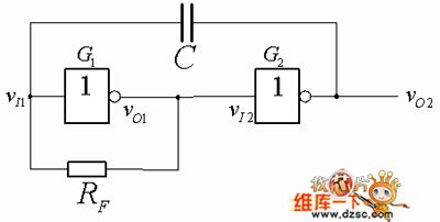
Asymmetrical multivibrator is the simplified form of symmetrical multivibrator [Figure 1]. This circuit only has a feedback resistor and a capacitive coupling. Feedback resistor forces static operating point to locate within the turning area of voltage transfer characteristics. That is to say that the static input level electricity is approximately equal to the output level electricity. So it is said that the static multivibrator is forced to work under the turning area of voltage transfer characteristics.
Feature1 Asymmetrical multivibrator circuit (View)
View full Circuit Diagram | Comments | Reading(500)
RC bridge oscillator circuit
Published:2011/6/4 12:36:00 Author:John | Keyword: RC bridge oscillator
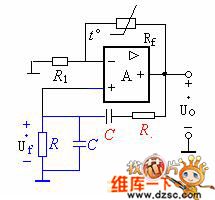
RC bridge oscillator circuit is just as shown in the figure. RC series-parallel network is connected to the output end and inverting input end of op-amp, aiming to form a positive feedback network with a frequency selective function. Besides, Rf and R1 are set within the op-amp's input end and its inverting input end. An integrated operational amplifier is connected with previous circuit to form a negative feedback amplifier circuit.
According to the following figure, the positive feedback circuit and negative feedback circuit form a Wien bridge circuit. And input and output terminals of the op-amp are connected across the bridge respectively. Therefore, this oscillation circuit is called RC bridge oscillator circuit.
(View)
View full Circuit Diagram | Comments | Reading(443)
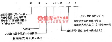
The connector and wiring circuit on the ground of Santana central connection box
Published:2011/5/14 23:56:00 Author:Borg | Keyword: connector, wiring circuit, Santana, connection box
The ground of the central connection box is the juncture of the wires throughout the whole car, of which 6 bundles are from instrument plate and front wall, 2 from car head, 1 from right-head, 1 from rear, and there are also some dual-point and single-point connectors whose position are as shown in Figure 1. It's useful to know the connector positions and wire codes for reading the following pictures.
There are two kinds of line codes as follows:
Letters are used to represent the strap connections. (View)
View full Circuit Diagram | Comments | Reading(364)
| Pages:79/164 At 206162636465666768697071727374757677787980Under 20 |
Circuit Categories
power supply circuit
Amplifier Circuit
Basic Circuit
LED and Light Circuit
Sensor Circuit
Signal Processing
Electrical Equipment Circuit
Control Circuit
Remote Control Circuit
A/D-D/A Converter Circuit
Audio Circuit
Measuring and Test Circuit
Communication Circuit
Computer-Related Circuit
555 Circuit
Automotive Circuit
Repairing Circuit